Display Subsystem
Display Subsystem
Overview
The KN5000 uses a 320x240 color LCD driven by an MN89304 VGA-compatible controller. The display shows menus, parameters, song information, and graphical elements. Display updates are driven by the firmware’s main event loop (not by a vertical blank interrupt).
Architecture
┌─────────────────────────────────────────────────────────────┐
│                        MAIN CPU                              │
│                                                              │
│  Graphics routines in Main ROM                              │
│  UI framework manages pages and widgets                     │
│  Display updates in main event loop (not VBI)               │
└─────────────────────────────────────────────────────────────┘
                              │
                              v
┌─────────────────────────────────────────────────────────────┐
│                    MN89304 VGA CONTROLLER                    │
│                                                              │
│  Memory-mapped I/O: 0x1703B0-0x1703DF                       │
│  Resolution: 320 x 240 pixels                                │
│  Color depth: 8-bit indexed (256 colors)                    │
│  RAMDAC: 4-bit per channel (12-bit RGB)                     │
│  Row offset: svga_device::offset() << 3 (8x multiplier)    │
└─────────────────────────────────────────────────────────────┘
                              │
                              v
┌─────────────────────────────────────────────────────────────┐
│                 VIDEO RAM (0x1A0000-0x1DFFFF)               │
│                                                              │
│  256KB linear framebuffer                                    │
│  Active area: 76,800 bytes (320 x 240 x 1 byte/pixel)      │
│  Row stride: 320 bytes                                       │
└─────────────────────────────────────────────────────────────┘
                              │
                              v
┌─────────────────────────────────────────────────────────────┐
│                      LCD PANEL                               │
│                                                              │
│  320 x 240 color TFT LCD                                    │
│  Backlit display                                             │
└─────────────────────────────────────────────────────────────┘
MN89304 VGA Controller
The MN89304 is a VGA-compatible LCD controller with some important differences from standard VGA:
Key Differences from Standard VGA
| Property | Standard VGA | MN89304 (KN5000) |
|---|---|---|
| DAC resolution | 6-bit per channel (0-63) | 4-bit per channel (0-15) |
| Palette color depth | 18-bit RGB | 12-bit RGB |
| Row pitch calculation | offset register value |
offset << 3 (8x multiplier) |
| I/O base | CPU port space | Memory-mapped at 0x170000 |
VGA Register Map
VGA I/O ports are memory-mapped to CPU address 0x170000 + port_number:
| VGA Port | CPU Address | Register | Access | Description |
|---|---|---|---|---|
| 0x3C0 | 0x1703C0 | Attribute Controller | W | Address/Data (alternating writes) |
| 0x3C2 | 0x1703C2 | Misc Output | W | Clock select, sync polarity |
| 0x3C3 | 0x1703C3 | VGA Enable | W | Global enable (write 0x01 to enable) |
| 0x3C4 | 0x1703C4 | Sequencer Index | W | Select sequencer register |
| 0x3C5 | 0x1703C5 | Sequencer Data | R/W | Sequencer register data |
| 0x3C6 | 0x1703C6 | DAC Mask | R/W | Palette mask (typically 0xFF) |
| 0x3C7 | 0x1703C7 | DAC Read Index | W | Select palette entry for reading |
| 0x3C8 | 0x1703C8 | DAC Write Index | W | Select palette entry for writing |
| 0x3C9 | 0x1703C9 | DAC Data | R/W | RGB data (3 sequential bytes per entry) |
| 0x3CE | 0x1703CE | Graphics Controller Index | W | Select GC register |
| 0x3CF | 0x1703CF | Graphics Controller Data | R/W | GC register data |
| 0x3D4 | 0x1703D4 | CRTC Index | W | Select CRTC register |
| 0x3D5 | 0x1703D5 | CRTC Data | R/W | CRTC register data |
| 0x3DA | 0x1703DA | Input Status 1 | R | Vertical retrace status |
VGA Initialization Values
The VGA_Setup routine (0xEF51A5) configures the full register set at boot. Key values:
Sequencer Registers (via ports 0x3C4/0x3C5):
| Index | Value | Description |
|---|---|---|
| 0x00 | 0x03 | Reset (synchronous) |
| 0x01 | 0x21 | Clocking Mode (screen off during init; 0x01 = screen on) |
| 0x02 | 0x0F | Map Mask (all 4 planes enabled) |
| 0x03 | 0x00 | Character Map Select |
| 0x04 | 0x06 | Memory Mode (chain-4, no odd/even) |
| 0x06-0x11 | various | MN89304 extended registers (LCD timing) |
CRTC Timing Registers (via ports 0x3D4/0x3D5):
| Index | Value | Description |
|---|---|---|
| 0x00 | 0x65 | Horizontal Total (101 chars) |
| 0x01 | 0x27 | Horizontal Display End (39 chars = 320px/8) |
| 0x04 | 0x28 | Start Horizontal Retrace |
| 0x05 | 0x29 | End Horizontal Retrace |
| 0x06 | 0xF3 | Vertical Total (243 lines) |
| 0x07 | 0x00 | Overflow |
| 0x10 | 0xF2 | Vertical Retrace Start (242) |
| 0x11 | 0x03→0x80 | Vertical Retrace End (unlock→lock CRTC 0-7) |
| 0x12 | 0xEF | Vertical Display End (239 = 240 lines) |
| 0x13 | 0x14 | Offset (20 × 8 = 160 words = 320 bytes/row) |
| 0x15 | 0xEF | Start Vertical Blanking |
| 0x16 | 0xF3 | End Vertical Blanking |
| 0x17 | 0xE3 | Mode Control |
| 0x18 | 0xFF | Line Compare |
| 0x19 | 0x00 | MN89304-specific |
| 0x1A | 0x10 | MN89304-specific |
Graphics Controller (via ports 0x3CE/0x3CF):
| Index | Value | Description |
|---|---|---|
| 0x01 | 0x00 | Enable Set/Reset |
| 0x03 | 0x00 | Data Rotate |
| 0x04 | 0x00 | Read Map Select |
| 0x05 | 0x00 | Graphics Mode |
| 0x06 | 0x01 | Miscellaneous (chain odd/even) |
| 0x08 | 0xFF | Bit Mask |
Misc Output: 0xE3 (25 MHz dot clock, negative H/V sync, 60 Hz)
Boot DAC Palette (9 basic colors):
| Index | R | G | B | Color |
|---|---|---|---|---|
| 0 | 0 | 0 | 0 | Black |
| 1 | F | F | F | White |
| 2 | F | 0 | 0 | Red |
| 3 | 0 | F | 0 | Green |
| 4 | 0 | 0 | F | Blue |
| 5 | 0 | F | F | Cyan |
| 6 | F | F | 0 | Yellow |
| 7 | F | 0 | F | Magenta |
| 8 | 0 | 0 | 4 | Dark Blue |
Palette Programming
The MN89304 uses a 4-bit RAMDAC (implemented as pal4bit() in MAME). Only the lower 4 bits of each color component value are significant:
// Writing a 256-color palette
for (int i = 0; i < 256; i++) {
    *(volatile uint8_t*)0x1703C8 = i;            // Select entry
    *(volatile uint8_t*)0x1703C9 = red[i] >> 4;  // 4-bit R (from 8-bit)
    *(volatile uint8_t*)0x1703C9 = green[i] >> 4; // 4-bit G
    *(volatile uint8_t*)0x1703C9 = blue[i] >> 4;  // 4-bit B
}
Palette data format notes:
- The HDAE5000 firmware stores palette data as 8-bit RGB and shifts right by 4 during loading
- If palette data is stored in 6-bit VGA format (0-63), shift right by 2 instead
- Effective color resolution: 4096 colors (16 levels per channel)
CRTC Start Address
The CRTC start address determines which VRAM byte appears at the top-left pixel:
| CRTC Register | Index | Description |
|---|---|---|
| Start Address High | 0x0C | High byte of VRAM start offset |
| Start Address Low | 0x0D | Low byte of VRAM start offset |
The firmware initializes the CRTC start address to 0x0000, meaning VRAM address 0x1A0000 corresponds to screen pixel (0,0).
// Reading current CRTC start address
*(volatile uint8_t*)0x1703D4 = 0x0C;
uint8_t start_high = *(volatile uint8_t*)0x1703D5;
*(volatile uint8_t*)0x1703D4 = 0x0D;
uint8_t start_low = *(volatile uint8_t*)0x1703D5;
uint16_t crtc_start = (start_high << 8) | start_low;
Row Offset Override
The MN89304 overrides the standard VGA row offset calculation with an 8x multiplier:
// In MAME: mn89304::offset()
uint32_t mn89304::offset() {
    return svga_device::offset() << 3;
}
This means the CRTC offset register value is multiplied by 8 to get the actual byte offset per row. The default configuration results in a 320-byte row stride (matching the 320-pixel width).
Video RAM
| Property | Value |
|---|---|
| Base address | 0x1A0000 |
| Size | 256KB (0x1A0000-0x1DFFFF) |
| Active display area | 76,800 bytes (320 x 240) |
| Pixel format | 8-bit indexed color (1 byte per pixel) |
| Row stride | 320 bytes |
| Pixel addressing | VRAM_BASE + y * 320 + x |
The framebuffer is linear and row-major. The active display occupies the first 76,800 bytes; the remaining ~185KB is unused but accessible.
Display Update Mechanism
Main Loop Driven (Not VBI)
The firmware’s display updates are not driven by a vertical blank interrupt. Instead, they occur as part of the main event loop at MainLoop:
Main Event Loop (MainLoop)
    |
    +-- Control Panel Poll
    +-- Display Update          <-- firmware draws its UI
    +-- MIDI Processing
    +-- FDC Handler
    +-- HDAE5000 Frame_Handler  <-- extension ROM callback
    +-- Audio Sync
    |
    (loop)
This means:
- Display updates happen at the main loop rate (not at a fixed refresh rate)
- The HDAE5000 Frame_Handler runs after the firmware’s display update
- Any VRAM writes by extension code will be overwritten on the next loop iteration unless the firmware’s drawing is disabled
Display Disable Flag
The firmware checks a flag byte at address 0x0D53 before performing display updates. Setting bit 3 of this byte disables all firmware-driven LCD rendering:
; At 0xEF77DF (main display update gate):
BIT 3, (0D53h)           ; Check display disable flag
JRL Z, skip              ; If bit 3 CLEAR, skip display entirely
CALL Display_ResetDirtyFlags
; ... dispatches via state byte (0D65h) ...
CALL Display_UpdateDirtyRegions
This check occurs at four firmware locations (0xEF77DF, 0xEFAA40, 0xF59C11, 0xF59D65), gating all display update code paths. When bit 3 is set, the firmware skips dirty-region tracking, state-based display dispatch, and VRAM writes — allowing an extension ROM to take full control of the framebuffer. See HDAE5000 Homebrew for usage details.
Workspace Display Callbacks
The firmware’s workspace dispatch system provides display-related callbacks accessible via Handler Table A:
| Offset | Purpose | Notes |
|---|---|---|
| +0x0124 | Display callback | Display state management |
| +0x0278 | Display state | Display mode/state queries |
| +0x0534 | Display update | Trigger display refresh |
These callbacks are used by the original HDAE5000 firmware for integrating its UI with the main firmware’s display system. Their exact protocols are under investigation.
Drawing Primitives
The firmware implements a complete graphics library for rendering to offscreen buffers. All drawing targets OFFSCREEN_BUFFER_1 (0x43C00) by default, which is then blitted to VRAM (0x1A0000) during the display update cycle.
Rendering Pipeline
All drawing functions follow a deferred command queue pattern:
Caller invokes DrawLine/DrawBox/DrawString/etc.
     │
     ├── IS_XSP_INSIDE_4K_REGION_AT_1C032 (0xFAA532)
     │   checks if caller is running in the draw task context
     │   (stack pointer in range 0x1C032 - 0x1D032)
     │
     ├── YES (draw task context):
     │   Execute DrawXxx_Impl directly
     │   Write pixels to OFFSCREEN_BUFFER_1 (0x43C00)
     │   Call SetChangeRect() to expand dirty bounding box
     │
     └── NO (other task context):
         Serialize parameters into DrawQueue (circular buffer)
         Call DisplayCmd_DequeueAndExecute
         → TaskSched_WaitForEvent(3) until draw task picks up command
         → Draw task executes command and signals completion
This ensures all VRAM/buffer writes happen in a single task context, avoiding concurrency issues.
Draw Command Queue
The draw queue is a circular buffer managed by DrawQueue_Alloc (0xFAA4ED):
| Property | Value |
|---|---|
| Base address | 0x030466 |
| Size | 8KB (0x2000 bytes) |
| Write pointer | 0x03246A |
| Read pointer | 0x032474 |
| Entry count | 0x03247A (modular counter, wraps at 0x7C entries) |
| Synchronization | Event 3 (wait/signal) + Event 4 (audio lock) |
Each queued command starts with a 4-byte function pointer (the DrawXxx_Impl address), followed by serialized parameters (8-28 bytes depending on the primitive). When the draw task processes a command, it calls the function pointer with the parameter block.
Graphics Initialization
InitializeGraphics (0xFAA4FA) performs the following at boot:
- Initialize draw task (
InitDrawTask) - Show screen group 5 and enable palette
- Initialize palette RGB tables (
InitPaletteRGB) - Set wallpaper (index 0) and palette (index 2)
- Clear two offscreen buffers (each 0x9600 = 38,400 bytes) at 0x43C00 with
Memset(0)
The two buffers at 0x43C00 and 0x4D200 (each 320x120 = 38,400 bytes) suggest a split-screen double-buffering scheme where the top and bottom halves of the 320x240 display are rendered independently.
Address Calculation
All drawing functions convert (x, y) pixel coordinates to buffer offsets using:
offset = y * 320 + x
The multiplication y * 320 is computed via shifts: (y << 2 + y) << 6 = y * 5 * 64. This is implemented in the shared helper Set_XWA_to_320_times_XDE at 0xEF5023.
Drawing Modes
Several primitives support multiple drawing modes specified by a mode code:
| Mode | Code | Operation | Description |
|---|---|---|---|
| Write | 0x201 | pixel = color |
Direct pixel write |
| Clear | 0x202 | pixel = 0x00 |
Clear pixel to zero |
| OR | 0x203 | pixel |= color |
Bitwise OR with color |
| AND | 0x204 | pixel &= color |
Bitwise AND with mask |
| XOR | 0x205 | pixel ^= color |
Bitwise XOR (used for cursors, selection) |
Special Colors
| Color | Meaning |
|---|---|
| 0xF7 | Transparent (pixel skipped, no write) |
| 0xF5 | Read-back: reads pixel from secondary buffer (pattern fill) |
Memory Operations
| Function | Address | Description |
|---|---|---|
Copy_DE_words_from_XBC_to_XWA |
0xEF18D7 | Block copy using LDIRW. Blits offscreen → VRAM |
Fill_memory_at_XWA_with_DE_words_of_BC_value |
0xEF18E0 | Fill memory with 16-bit pattern (buffer clear) |
Pixel Operations
| Function | Address | Description |
|---|---|---|
ReadPixel |
0xFAA7B4 | Read 8-bit color from offscreen buffer at (x, y) |
ModifyPixel |
0xFAA7E4 | Write single pixel to offscreen buffer |
ModifyPixelEx |
0xFAA84A | Extended pixel op: write/clear/OR/AND/XOR modes |
Rectangle Operations
| Function | Address | Description |
|---|---|---|
VRAM_FillRect |
0xEF50DF | Fill 6×12 pixel rect directly in VRAM with solid color |
DrawWall |
0xFABB74 | Fill entire screen from source buffer (wallpaper/splash) |
Line Drawing
| Function | Address | Description |
|---|---|---|
DrawLine |
0xFAA98A | Bresenham line from point A to point B |
DrawLineEx |
0xFAAA3E | Extended line with drawing mode (write/XOR/etc.) |
Both use Bresenham’s algorithm with optimized fast paths for horizontal lines (dy = 0), vertical lines (dx = 0), and general diagonal lines. The color 0xF5 triggers pattern-fill mode where each pixel’s color is read from a secondary buffer instead of using a fixed color.
Bitmap/Sprite Drawing
The firmware uses a bitmap descriptor table in ROM at 0x913000. Each entry is 8 bytes:
+0x00: word  width (pixels)
+0x02: word  height (rows)
+0x04: long  pixel_data_ptr (24-bit address of pixel data in ROM)
Bitmap pixel data is stored as packed 16-bit words (2 pixels per word). Color 0xF7 in bitmap data is treated as transparent (pixel skipped).
| Function | Address | Description |
|---|---|---|
DrawBitmap |
0xFABC3A | Draw bitmap with transparency (0xF7 = transparent) |
DrawBitmapFast |
0xFABE0E | Draw bitmap without transparency check (opaque only) |
MovePixels |
0xFABA60 | Copy rectangular pixel block within offscreen buffer |
Draw_FlashMemUpdate_message_bitmap |
0xEF5040 | Draw 224×22 monochrome (1bpp) bitmap for firmware update UI |
Text Rendering
Text is rendered using a font glyph table in ROM at 0x945C00. Each font entry is 16 bytes:
+0x00: word  char_width (pixels per character)
+0x02: word  char_height (pixels)
+0x04: word  descent (below baseline)
+0x06: word  ascent (above baseline)
+0x08: long  glyph_bitmap_ptr (1bpp bitmap data, 8 pixels per byte, MSB first)
+0x0C: long  kerning_table_ptr (0 = fixed-width font; see below)
For variable-width fonts (kerning_table_ptr ≠ 0), the kerning table has 4-byte entries per character: {word char_width, word glyph_data_offset}. Each glyph uses ceil(char_width/8) × height bytes at glyph_bitmap_ptr + glyph_data_offset.
Character codes are offset by 0x20 (space) before table lookup. Glyphs are rendered as 1bpp bitmaps decomposed into 8-pixel-wide vertical strips, drawn left-to-right, top-to-bottom. All text rendering clips against a specified rectangle.
| Function | Address | Description |
|---|---|---|
DrawString |
0xFACACE | Core text renderer: draws null-terminated string |
DrawStringCentered |
0xFACF17 | Center text horizontally and vertically in rect |
DrawStringLeftJustify |
0xFACFBA | Left-align text (x = rect.left + 4), center vertically |
DrawStringRightJustify |
0xFAD004 | Right-align text (x = rect.right - 4 - width) |
DrawStringAlignment |
0xFAD052 | Dispatch by mode: 0=center, 1=left, 2=right |
DrawStringReverse |
0xFAD091 | Draw with swapped fg/bg colors (selection highlight) |
Font Helper Functions
| Function | Address | Description |
|---|---|---|
GetCharHeight |
0xFB25ED | Return character height from font table (+0x02) |
GetCharDescent |
0xFB25F9 | Return character descent from font table (+0x04) |
CalcTotalWidth |
0xFB270D | Calculate total pixel width of rendered string |
ConvertStrings |
0xFB264F | Convert control codes to displayable format (0x7E prefix = escape) |
WordwrapStrings |
0xFB26D2 | Word-wrap text for multi-line layout |
Character Encoding
Characters use ASCII encoding with an offset of 0x20 (space). Before lookup in the font or kerning table, each character code has 0x20 subtracted. Control characters below 0x20 are mapped to space.
Escape sequences: The 0x7E prefix byte introduces a two-digit hex-encoded character code:
0x7E 0x33 0x41  →  character 0x3A (colon)
0x7E 0x46 0x37  →  character 0xF7 (special symbol)
Hex digits support 0-9, a-f, and A-F.
Font Catalog
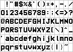
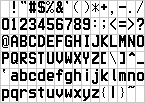
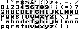
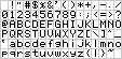
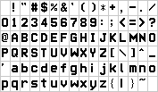
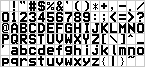
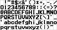
The firmware contains 10 fonts (IDs 0-9) in the Table Data ROM. Each font has 224 characters (ASCII 0x20-0xFF). All glyph data resides at 0x945C00-0x94FF00.
| ID | Size | Type | Kerning | Description |
|---|---|---|---|---|
| 0 | 8×16 | Fixed | No | Standard UI font |
| 1 | 8×16 | Fixed | No | Standard UI font (bold variant) |
| 2 | 16×16 | Fixed | No | Wide/bold font (double-width) |
| 3 | 6×8 | Fixed | No | Small font (compact displays) |
| 4 | 11×16 | Fixed | No | Medium-wide font |
| 5 | var×16 | Variable | Yes | Proportional font (widths 3-10px) |
| 6 | 8×10 | Fixed | No | Compact font (reduced height) |
| 7 | 8×16 | Fixed | No | Standard UI font (alternate style) |
| 8 | 8×16 | Fixed | No | Standard UI font (alternate bold) |
| 9 | 11×16 | Fixed | No | Medium-wide font (alternate) |
Variable-width font (ID 5): Uses a kerning table at 0x94C620 with 4-byte entries per character: {word char_width, word glyph_offset}. Each glyph uses ceil(width/8) × height bytes. Character widths range from 3 to 10 pixels.
Font samples (extracted from ROM):
Font 0:
Font 1:
Font 2:
Font 3:
Font 4:

Font 5:
Font 6:
Font 7:

Font 8:

Font 9:
BDF (Bitmap Distribution Format) exports are available in the roms-disasm repository for use in emulators and tools.
Screen Layout and Regions
Region Architecture
The display is divided into 11 independently-tracked dirty regions. Each region has its own redraw function and dirty bit. The regions are not defined by hardcoded pixel coordinates — instead, each redraw function loads ROM descriptor tables that define the region geometry, content, and rendering parameters. These descriptors are passed to UI rendering helper functions.
Region Update Order
Display_UpdateDirtyRegions (0xEF5B36) updates regions in a specific order optimized for visual priority:
1. Region 0  - Status Bar         (mode indicators, tempo)
2. Region 5  - Menu Area          (menu/list content)
3. Region 7  - Parameter Display  (parameter names)
4. Region 8  - Value Display      (parameter values)
5. Region 9  - Indicator Area     (status indicators)
6. Region 1  - Title Bar          (song/patch name, up to 3 title fields)
7. Region 10 - Footer Area        (status/help text)
8. Region 6  - Button Labels      (soft button labels, 3 rows of 8)
9. Region 3  - Main Content       (primary display area)
10. Region 4 - Side Panel         (side parameters)
11. Region 2 - Selection          (highlight/cursor, drawn last for overlay)
Redraw Functions
Each region has a dedicated redraw function that references ROM descriptor tables:
| Region | Redraw Function | Address | ROM Descriptors (examples) |
|---|---|---|---|
| 0 | Display_RedrawStatusBar |
0xF00999 | 0xE0B905, 0xE0B92E, 0xE0B99D |
| 1 | Display_RedrawTitleBar |
0xF00C89 | 0xE0BD52-0xE0BD7A (3 title fields) |
| 2 | Display_RedrawSelection |
0xF00DA5 | Variable (cursor overlay) |
| 3 | Display_RedrawMainContent |
0xF00C33 | 0xE0BD89 |
| 4 | Display_RedrawSidePanel |
0xF00E35 | Multiple descriptor sets |
| 5 | Display_RedrawMenu |
0xEFF110 | Complex menu rendering |
| 6 | Display_RedrawButtonLabels |
0xF00FDC | 0xE0C764, 0xE0C8CC, 0xE0BF6E |
| 7 | Display_RedrawParameters |
0xEF6F1A | State-dependent |
| 8 | Display_RedrawValues |
0xEF6FA3 | State-dependent |
| 9 | Display_RedrawIndicators |
0xEF704B | State-dependent |
| 10 | Display_RedrawFooter |
0xF00C4A | 0xE0BDAC, 0xE0BDE8, 0xE0BE06 |
Display State
The display state byte at address 0x0D65 (SFR 3429) selects the active screen mode:
| Value | Mode |
|---|---|
| 0 | Default/normal display |
| 2 | Alternative layout (different descriptor sets used) |
The state byte influences which ROM descriptors are selected by redraw functions, allowing the same regions to display different content based on the active screen mode.
UI Rendering Helpers
The redraw functions delegate to specialized rendering helpers:
| Helper | Address | Purpose |
|---|---|---|
Scoop_EventLoop_12Entry |
0xF0212C | General UI element renderer |
GraphicsRender_Start |
0xFB15F6 | Two-descriptor pair renderer |
GraphicsRender_ProcessEntries |
0xFB1594 | Simple descriptor renderer |
Scoop_CurveUpdate_SegmentEnd |
0xF01930 | Content area renderer |
Scoop_GlideParam_Setup |
0xF01DAB | Number/value display renderer |
Scoop_EventLoop_36Entry |
0xF023CF | Dynamic value renderer |
DrawFunc_Init |
0xFB2044 | Parameter display renderer |
ColorBlit_WithPaletteSave |
0xFB24CB | Status indicator renderer |
Button Label Organization
Region 6 (button labels) manages three rows of 8 soft-button labels, organized at RAM addresses:
- Row 1: 0x0E55 (8 entries, 4 bytes apart)
- Row 2: 0x0E75 (8 entries, 4 bytes apart)
- Row 3: 0x0E95 (8 entries, 4 bytes apart)
Dirty Region Tracking
The display update system tracks 11 independent screen regions. Each region has a dirty bit in the bitmap at DISPLAY_DIRTY_FLAGS (0x205E4):
| Function | Address | Description |
|---|---|---|
Display_ResetDirtyFlags |
0xEF5B27 | Clear all dirty flags and enable flag |
Display_UpdateDirtyRegions |
0xEF5B36 | Check all 11 regions, call redraw for dirty ones |
Display_UpdateRegion0 |
0xEF5B8B | Status bar |
Display_UpdateRegion1 |
0xEF5BE9 | Title bar |
Display_UpdateRegion2 |
0xEF5C20 | Selection highlight |
Display_UpdateRegion3 |
0xEF5C07 | Main content area |
Display_UpdateRegion4 |
0xEF5C39 | Side panel |
Display_UpdateRegion5 |
0xEF5C52 | Menu area |
Display_UpdateRegion6 |
0xEF5C6B | Button labels |
Display_UpdateRegion7 |
0xEF5C84 | Parameter display |
Display_UpdateRegion8 |
0xEF5C9D | Value display |
Display_UpdateRegion9 |
0xEF5CB6 | Indicator area |
Display_UpdateRegion10 |
0xEF5CCF | Footer area |
Change Tracking
| Function | Address | Description |
|---|---|---|
SetChangeRect |
0xFAA760 | Expand dirty bounding box to include drawn region |
The bounding box is maintained at:
| Address | Purpose |
|---|---|
| 0x030456 | Min X (left edge) |
| 0x030458 | Min Y (top edge) |
| 0x03045A | Max X (right edge) |
| 0x03045C | Max Y (bottom edge) |
| 0x03045E | Update flag (non-zero = needs refresh) |
Offscreen Buffers
| Buffer | Address | Size | Purpose |
|---|---|---|---|
| OFFSCREEN_BUFFER_1 | 0x043C00 | 76,800 bytes | Primary render target (all drawing goes here) |
| OFFSCREEN_BUFFER_2 | 0x056800 | 76,800 bytes | Secondary buffer (scrolling/animation) |
| OFFSCREEN_BUFFER_3 | 0x05FE00 | 76,800 bytes | Tertiary buffer (compositing) |
| OFFSCREEN_BUFFER_4 | 0x069400 | 76,800 bytes | Quaternary buffer (sprites/overlays) |
UI Widget Rendering
Rectangle & Shape Primitives
In addition to the pixel-level drawing primitives, the firmware provides higher-level shape drawing functions:
| Function | Address | Description |
|---|---|---|
DrawBox |
0xFAB295 | Fill a rectangle with solid color (clip to 0-319, 0-239) |
DrawFrame |
0xFAB400 | Draw rectangle outline (4 border lines, no fill) |
DrawFrameEx |
0xFAB8CC | Styled frame with XOR support and screen clipping |
DrawDesignFrame |
0xF9C8B7 | Decorative frame with special border patterns |
DrawDesignBox |
0xFAD559 | Styled box with type-specific rendering |
Icon Rendering
The firmware maintains a separate icon descriptor table at 0x938000 (in Table Data ROM), using the same 8-byte format as the bitmap table:
| Function | Address | Description |
|---|---|---|
DrawIcons |
0xFABF61 | Draw icon from table at 0x938000 |
DrawBitmapSP |
0xFAC0CB | Draw bitmap with special color mapping |
DrawBitmapSPFast |
0xFAC1FF | Fast special bitmap rendering |
DrawBitmapSP2 |
0xFAC38D | Alternative special bitmap variant |
DrawBitmapFile |
0xFAC3FB | Draw bitmap from file/external data |
Progress Bar Widgets
| Function | Address | Description |
|---|---|---|
DrawProgressRectH |
0xF99E75 | Horizontal progress bar (3 modes: center, left, right fill) |
DrawProgressRectV |
0xF99F7D | Vertical progress bar (3 modes: center, top, bottom fill) |
Widget Event Handlers
The firmware implements widget-specific event handlers following a *Proc naming convention:
| Widget Type | Handler | Description |
|---|---|---|
| GroupBox | GroupBoxProc |
Container/panel widget |
| Label | LabelProc |
Static text display |
| EditSwitch | EditSwProc |
Toggle/checkbox control |
| TextBox | TextBoxProc |
Text input field |
Many domain-specific widget types exist for the keyboard’s various modes (arrangement, composition, bank selection, etc.).
LCD Control
| Function | Address | Description |
|---|---|---|
LcdOn |
0xFAA5D0 | Enable LCD output (set flag at 0x030464) |
LcdOff |
0xFAA5DB | Disable LCD output |
ChangePalette |
0xFAF34E | Switch color palette |
ChangeWall |
0xFAF21C | Load background wallpaper |
ChangeWallPalette |
0xFAF26C | Change palette for wallpaper |
Embedded Images
Images extracted from firmware ROMs:
| Source | Count | Description |
|---|---|---|
| Main CPU ROM | 42 | UI elements, logos, demo graphics |
| HDAE5000 ROM | 4 | Product logo, file panel graphics |
See Image Gallery for all extracted images.
Display Modes
The KN5000 uses a single display mode:
| Property | Value |
|---|---|
| Width | 320 pixels |
| Height | 240 pixels |
| Color Depth | 8-bit (256 color palette) |
| RAMDAC | 4-bit per channel (12-bit effective RGB) |
| Refresh | Main-loop driven (not fixed rate) |
Related Pages
- HDAE5000 Homebrew Development - Display ownership for custom ROMs
- Image Gallery - Extracted firmware graphics
- UI Framework - Menu and widget system
- Hardware Architecture - Physical components
- System Overview - Overall architecture
Animation and Transition Effects
The KN5000 implements several animation and transition effect mechanisms, all software-based (no hardware scroll registers are used).
Rendering Pipeline
All drawing operations target OFFSCREEN_BUFFER_1 (0x43C00), never VRAM directly. The UpdateScreen function (0xFAA61D) copies changed regions to VRAM:
Drawing Operation (DrawString, DrawBox, etc.)
        ↓
Write to OFFSCREEN_BUFFER_1 (0x43C00)
        ↓
Call SetChangeRect() → expand dirty bounding box at 0x030456
        ↓
Main loop calls UpdateScreen (0xFAA61D)
        ↓
Check dirty bounding box:
  Full screen? → full-screen blit (0xFB30A9)
  Partial?     → row-by-row blit (0xFB30D3)
        ↓
Copy from 0x43C00 → VRAM at 0x1A0000
        ↓
Reset dirty box and flags
During large updates, VGA_ScreenBlank (0xFB319A) blanks the display by setting VGA Sequencer register 01h bit 5, preventing visible tearing. VGA_ScreenUnblank (0xFB318A) re-enables display after the update.
Palette-Based Fade Effects
The firmware implements fade effects through VGA DAC palette manipulation:
| Function | Address | Description |
|---|---|---|
| ChangePalette | 0xFAF2F3 | Switch to a new 256-color palette from table at 0xEAAE66 |
| PaletteBankRotation | 0xFAF346 | Rotate pixel values through palette banks for fade effect |
Palette table at 0xEAAE66: entries are 10 bytes each, containing pointers to RGB palette data. The firmware supports 16 palette banks of 16 colors each (0x00-0x0F through 0xE0-0xEF).
Palette bank rotation (0xFAF346) creates fade effects by modifying pixel color indices:
- Pixels with value >= 0xE0: subtract 0x90 (wrap to lower bank)
- Pixels with value < 0xE0: add 0x10 (shift to next bank)
This rotates all pixels one palette bank forward. Combined with palettes arranged as intensity gradients, this produces smooth brightness fade transitions.
Key palette state addresses:
| Address | Purpose |
|---|---|
| 0x03EF94 | Current palette data pointer |
| 0x03EF9E | Current palette index |
| 0x03EFA0 | Previous palette index (for partial updates) |
| 0x030460 | Palette update pending flag |
Grid-Based Screen Transitions
Complex screen transitions use a grid-based dissolve effect:
| Function | Address | Description |
|---|---|---|
| AcFadeSetGridBoxProc | 0xF7514A | Grid fade effect processor (event-driven) |
| FadeSetGridCheck | 0xF75377 | Grid parameter validation and dispatch |
| TtFadeInOut | 0xF75118 | Fade-in/out state machine (Entertainer mode) |
The grid effect divides the screen into cells and fades them individually with staggered timing, creating a “dissolve” appearance. Configuration uses ROM lookup tables:
0xE7F948— fade-in timing table0xE7F956— fade-out timing table0xE7F964— jump table for 7 sub-handlers (events 0x17-0x1D)
Pre-Computed Fade Data
Four binary data blobs in ROM store pre-computed fade transition patterns:
| Label | Address | Size | Purpose |
|---|---|---|---|
| Bitmap_FadeInPicture | 0xEB8072 | 2800 | Picture fade-in transition data |
| Bitmap_FadeInText | 0xEB8B62 | 1440 | Text fade-in transition data |
| Bitmap_FadeOutPicture | 0xEB9102 | 2850 | Picture fade-out transition data |
| Bitmap_FadeOutText | 0xEB9C24 | 2160 | Text fade-out transition data |
Timer-Driven Animation
Animation timing is handled by the IvOneShotTimerProc (0xF8A122) event handler, which provides single-shot timer callbacks for UI animation frame ticks.
Screen Transition State Machine
The SeqState_TransitionMode (0xF99579) handler manages full-screen mode transitions (e.g., switching between sequencer screens, entering demo mode). It coordinates state variables at:
0x02749A— transition progress counter0x02749E— transition timer0x0274A2— transition type/flags0x0274A8-0x0274AE— additional transition parameters
Scrolling
All scrolling is software-based — no VGA hardware scroll registers are used. Scrolling is implemented via MovePixels (0xFABA60), which copies rectangular pixel blocks within the offscreen buffer. The AcRotStrBoxProc (0xF8D6D8) handler provides smooth scrollbar animation with timer-based auto-repeat.
UI element names “SlideMove” and “SlideBase” appear in the firmware’s string table (0xEAB8D8), suggesting slide animation support for UI transitions.
MAME Emulation Status
| Component | Status | Notes |
|---|---|---|
| MN89304 VGA Controller | Working | Register map emulated, 320×240 8bpp LCD output |
| VRAM | Working | 256KB at 0x1A0000-0x1DFFFF, linear framebuffer |
| Palette | Working | 256-color palette with 4-bit RAMDAC (VGA DAC at 0x170000) |
| Display output | Working | Full screen rendering visible, UI widgets draw correctly |
| Font rendering | Working | All firmware text drawing functions operate correctly |
| Page transitions | Partial | Palette fade works; grid dissolve not verified |
The display is one of the most complete subsystems in MAME emulation. The MN89304 VGA controller is emulated as a custom device with the KN5000-specific RAMDAC and offset override behaviors.
Research Needed
- Document VGA register map at 0x170000 — Complete: full register set with init values
- Document VGA initialization sequence (boot-time register programming) — Complete
- Analyze framebuffer memory layout
- Understand display update mechanism (main loop, not VBI)
- Document MN89304 differences from standard VGA (4-bit RAMDAC, offset override)
- Identify display disable mechanism (0x0D53 bit 3)
- Identify font rendering routines (DrawString family, font table at 0x945C00)
- Document text drawing functions (DrawString, Centered, Left/Right, Reverse, Alignment)
- Map UI widget drawing primitives (pixel, line, rect, bitmap, text, blit)
- Document page transition effects (palette fade, grid dissolve, state machine)
Document deferred draw command queue– Complete: DrawQueue circular buffer, task context check, synchronization- Document workspace display callbacks (0x0124, 0x0278, 0x0534) protocols
- Reverse engineer pre-computed fade data format (BitmapFadeIn/Out blobs)
Code References
Core Display
| Symbol | Address | Purpose |
|---|---|---|
Display_ResetDirtyFlags |
0xEF5B27 |
Clear all dirty flags |
Display_UpdateDirtyRegions |
0xEF5B36 |
Check and redraw dirty regions |
UpdateScreen |
0xFAA61D |
Copy changed regions to VRAM |
Set_XWA_to_320_times_XDE |
0xEF5023 |
Y×320 coordinate calculation |
VGA_ScreenBlank |
0xFB319A |
Blank display during updates |
VGA_ScreenUnblank |
0xFB318A |
Restore display after updates |
LcdOn |
0xFAA5D0 |
Enable LCD output |
LcdOff |
0xFAA5DB |
Disable LCD output |
DrawQueue_Alloc |
0xFAA4ED |
Allocate space in deferred draw queue |
DisplayCmd_DequeueAndExecute |
0xFAA36A |
Process queued draw command in draw task |
IS_XSP_INSIDE_4K_REGION_AT_1C032 |
0xFAA532 |
Check if caller runs in draw task context |
InitializeGraphics |
0xFAA4FA |
Boot-time graphics initialization |
DrawFunc |
0xFAA48C |
Generic draw function dispatch with deferred support |
Drawing Primitives
| Symbol | Address | Purpose |
|---|---|---|
ReadPixel |
0xFAA7B4 |
Read pixel from offscreen buffer |
ModifyPixel |
0xFAA7E4 |
Write single pixel |
ModifyPixelEx |
0xFAA84A |
Write/clear/OR/AND/XOR pixel |
DrawLine |
0xFAA98A |
Bresenham line drawing |
DrawLineEx |
0xFAAA3E |
Line with drawing mode |
DrawBox |
0xFAB295 |
Filled rectangle |
DrawFrame |
0xFAB400 |
Rectangle outline |
DrawFrameEx |
0xFAB8CC |
Styled frame with XOR |
VRAM_FillRect |
0xEF50DF |
Direct VRAM rectangle fill |
SetChangeRect |
0xFAA760 |
Expand dirty bounding box |
Copy_DE_words_from_XBC_to_XWA |
0xEF18D7 |
Block memory copy (blit) |
Bitmap & Sprite
| Symbol | Address | Purpose |
|---|---|---|
DrawBitmap |
0xFABC3A |
Bitmap with transparency (0xF7) |
DrawBitmapFast |
0xFABE0E |
Opaque bitmap (no transparency) |
DrawIcons |
0xFABF61 |
Icon from table at 0x938000 |
MovePixels |
0xFABA60 |
Copy rectangular pixel block |
DrawWall |
0xFABB74 |
Full-screen wallpaper fill |
Draw_FlashMemUpdate_message_bitmap |
0xEF5040 |
1bpp update UI bitmap renderer |
Text
| Symbol | Address | Purpose |
|---|---|---|
DrawString |
0xFACACE |
Core text renderer |
DrawStringCentered |
0xFACF17 |
Center-aligned text |
DrawStringLeftJustify |
0xFACFBA |
Left-aligned text |
DrawStringRightJustify |
0xFAD004 |
Right-aligned text |
DrawStringReverse |
0xFAD091 |
Reversed fg/bg colors |
CalcTotalWidth |
0xFB270D |
Calculate string pixel width |
Display Regions
| Symbol | Address | Purpose |
|---|---|---|
Display_RedrawStatusBar |
0xF00999 |
Region 0: Status bar |
Display_RedrawTitleBar |
0xF00C89 |
Region 1: Title bar |
Display_RedrawSelection |
0xF00DA5 |
Region 2: Selection highlight |
Display_RedrawMainContent |
0xF00C33 |
Region 3: Main content |
Display_RedrawSidePanel |
0xF00E35 |
Region 4: Side panel |
Display_RedrawMenu |
0xEFF110 |
Region 5: Menu area |
Display_RedrawButtonLabels |
0xF00FDC |
Region 6: Button labels |
Display_RedrawParameters |
0xEF6F1A |
Region 7: Parameter display |
Display_RedrawValues |
0xEF6FA3 |
Region 8: Value display |
Display_RedrawIndicators |
0xEF704B |
Region 9: Indicators |
Display_RedrawFooter |
0xF00C4A |
Region 10: Footer |
Palette & Effects
| Symbol | Address | Purpose |
|---|---|---|
ChangePalette |
0xFAF34E |
Switch color palette |
ChangeWall |
0xFAF21C |
Load wallpaper |
PaletteBankRotation |
0xFAF346 |
Fade via palette bank rotation |
AcFadeSetGridBoxProc |
0xF7514A |
Grid dissolve transition |
SeqState_TransitionMode |
0xF99579 |
Full-screen mode transition |
DrawProgressRectH |
0xF99E75 |
Horizontal progress bar |
DrawProgressRectV |
0xF99F7D |
Vertical progress bar |
How to Contribute
See Help Wanted for contribution guidelines.
The HDAE5000 ROM has documented VGA palette setup at 0x28F8E0 which can serve as a reference for understanding the display interface.