HDAE5000 Homebrew Development
Writing Custom HDAE5000 Extension ROMs
The HD-AE5000 extension slot can run custom code on the KN5000’s main CPU. By replacing the HDAE5000 ROM with a custom binary, you can create games, demos, or utilities that run on the keyboard hardware. This page documents the extension ROM protocol, known toolchain bugs, and a working build pipeline.
Status: A Minesweeper game is fully playable on the KN5000 LCD via the HDAE5000 extension slot. Boot initialization, handler registration, DISK MENU entry with custom icon, game activation via button press, palette loading, and VRAM rendering are all working in MAME. The firmware’s object dispatch system, handler registration protocol, and event dispatch are fully implemented. Remaining work: control panel input during gameplay.
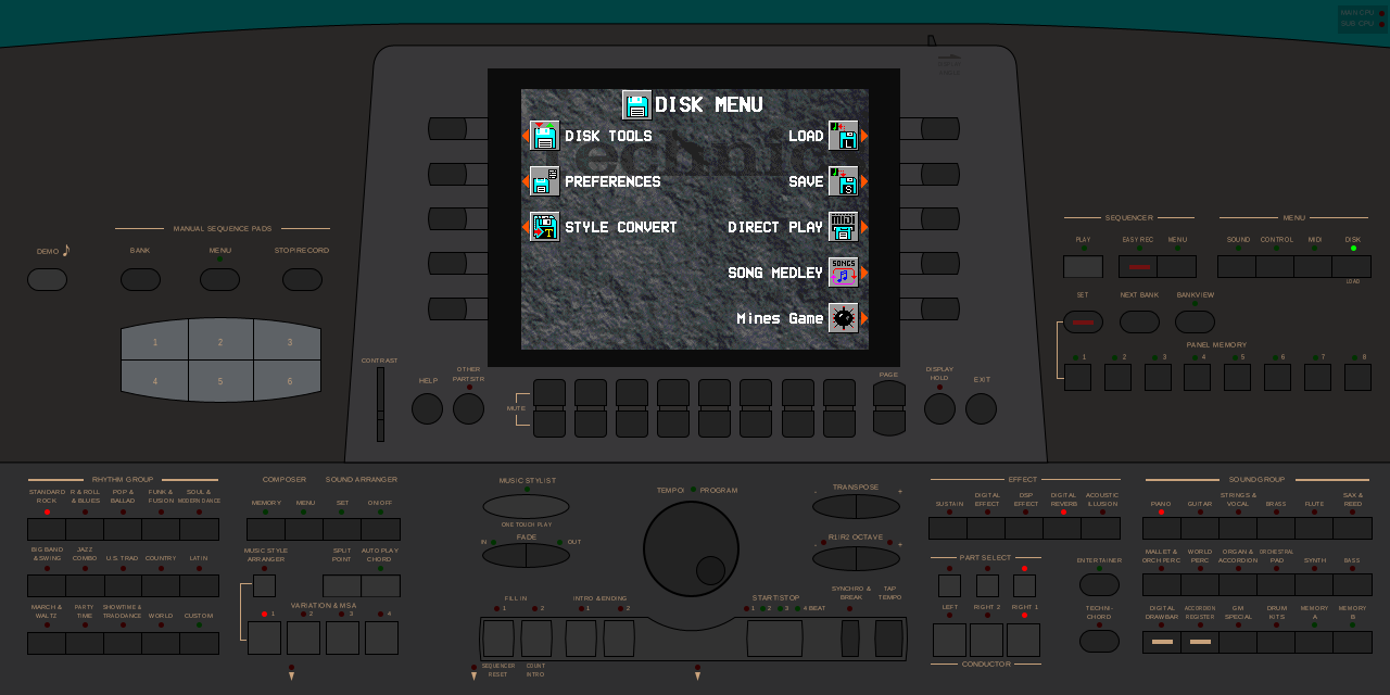 The KN5000 DISK MENU in MAME showing the “Mines Game” entry with a custom mine icon at the bottom-right position. Selecting this entry activates the game.
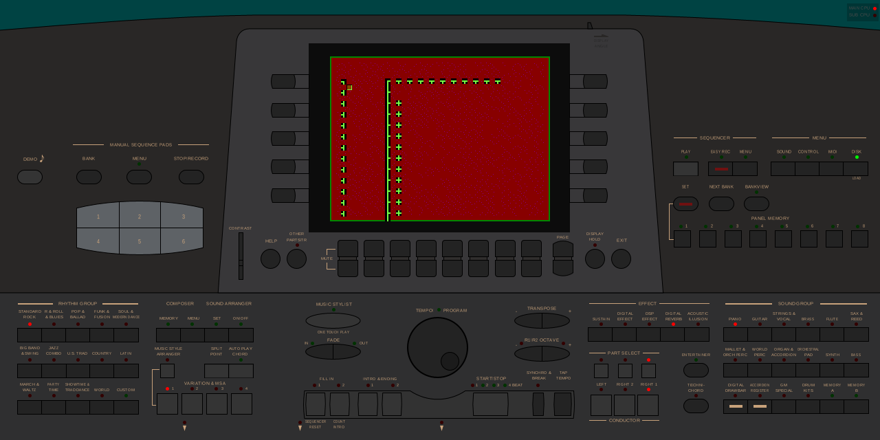 Minesweeper game rendering on the KN5000 LCD screen after activation from the DISK MENU. The green border, red minefield, and yellow tile markers are drawn by the extension ROM’s game code.
Prerequisites
- LLVM with TLCS-900 backend – a custom LLVM build with the TLCS-900 target
- MAME with KN5000 driver for testing
- Knowledge of the HDAE5000 firmware protocol
Quick Start
This section walks through building a minimal “hello world” extension ROM that draws a colored rectangle on the KN5000 LCD. For the full protocol details, see the sections below.
1. Set Up the Toolchain
# Build LLVM with TLCS-900 backend
git clone https://github.com/felipesanches/llvm-project.git -b tlcs900_backend
cd llvm-project
mkdir build && cd build
cmake -G Ninja ../llvm -DLLVM_TARGETS_TO_BUILD="TLCS900" \
  -DLLVM_ENABLE_PROJECTS="clang;lld" -DCMAKE_BUILD_TYPE=Release
ninja
2. Create the Project Structure
my_extension/
  startup.s       # XAPR header + entry points (assembly)
  main.c          # Your C code
  kn5000.ld       # Linker script
  Makefile
3. Minimal Startup Assembly (startup.s)
.equ VIDEO_RAM_BASE, 0x1A0000
.equ WORKSPACE_PTR,  0x200008
.equ GAME_ACTIVE,    0x200000
.equ STACK_TOP,      0x203000
.equ SAVED_SP,       0x200044

.globl GAME_ACTIVE
.globl yield_to_firmware

.section .startup, "ax", @progbits

; XAPR Header (8 bytes)
        .ascii  "XAPR"
        .byte   0x34, 0xA1, 0x2F, 0x00

; Entry Point 1: Boot_Init (offset 0x08)
        jp      Boot_Init
        ret
        .byte   0x00, 0x00, 0x00

; Entry Point 2: Frame_Handler (offset 0x10)
        jp      Frame_Handler
        ret
        .byte   0x00, 0x00, 0x00

; Entry Points 3-4: Unused
        ret
        .byte   0x00, 0x00, 0x00
        ret
        .byte   0x00, 0x00, 0x00

Boot_Init:
        ld      (WORKSPACE_PTR), xwa    ; Save workspace pointer
        ret

Frame_Handler:
        push    xwa
        push    xbc
        push    xde
        push    xhl
        push    xix
        push    xiy
        push    xiz

        ; Check if game is active
        ld      xhl, GAME_ACTIVE
        ld      xwa, (xhl)
        and     xwa, 0xFF
        cp      xwa, 0
        jrl     z, .Lframe_done

        ; First frame: set up stack and call main()
        ld      xwa, xsp
        ld      (SAVED_SP), xwa
        ld      xsp, STACK_TOP
        call    main

        ; main() returned — deactivate
        ld      xhl, GAME_ACTIVE
        ld      xwa, 0
        ld      (xhl), xwa
        ld      xwa, (SAVED_SP)
        ld      xsp, xwa

.Lframe_done:
        pop     xiz
        pop     xiy
        pop     xix
        pop     xhl
        pop     xde
        pop     xbc
        pop     xwa
        ret

; yield_to_firmware: save game context, return to firmware main loop.
; Firmware calls Frame_Handler next frame, which resumes here.
yield_to_firmware:
        ; (See Mines startup.s for full cooperative multitasking implementation)
        ret
4. Minimal C Code (main.c)
#include <stdint.h>

#define VRAM_BASE  ((volatile uint8_t *)0x1A0000)
#define LCD_WIDTH  320
#define LCD_HEIGHT 240

#define VGA_DAC_WRITE_INDEX ((volatile uint8_t *)0x1703C8)
#define VGA_DAC_DATA        ((volatile uint8_t *)0x1703C9)

void set_palette_entry(uint8_t index, uint8_t r, uint8_t g, uint8_t b) {
    *VGA_DAC_WRITE_INDEX = index;
    *VGA_DAC_DATA = r;  /* 6-bit values (0-63) */
    *VGA_DAC_DATA = g;
    *VGA_DAC_DATA = b;
}

void main(void) {
    /* Set palette: index 1 = bright green */
    set_palette_entry(1, 0, 63, 0);

    /* Draw a green rectangle */
    for (int y = 80; y < 160; y++) {
        for (int x = 100; x < 220; x++) {
            VRAM_BASE[y * LCD_WIDTH + x] = 1;
        }
    }

    /* Spin (in a real app, use yield_to_firmware() for cooperative multitasking) */
    while (1) {}
}
5. Linker Script (kn5000.ld)
MEMORY {
  ROM (rx)  : ORIGIN = 0x280000, LENGTH = 512K
  RAM (rwx) : ORIGIN = 0x200000, LENGTH = 12K
}
SECTIONS {
  .startup 0x280000 : { startup.o(.startup) } > ROM
  .text             : { *(.text*) } > ROM
  .rodata           : { *(.rodata*) } > ROM
  .data             : { *(.data*) } > RAM AT > ROM
  .bss              : { *(.bss*) } > RAM
}
6. Makefile
LLVM_BIN := /path/to/llvm-project/build/bin
CLANG    := $(LLVM_BIN)/clang
LLC      := $(LLVM_BIN)/llc
LLD      := $(LLVM_BIN)/ld.lld
OBJCOPY  := $(LLVM_BIN)/llvm-objcopy

CFLAGS   := -target tlcs900 -ffreestanding -nostdlib -O2
LLC_FLAGS := -mtriple=tlcs900 -mcpu=tmp94c241 -O2

BUILD    := build

all: $(BUILD)/extension.bin

$(BUILD):
	mkdir -p $(BUILD)

$(BUILD)/main.ll: main.c | $(BUILD)
	$(CLANG) $(CFLAGS) -S -emit-llvm -o $@ $<

$(BUILD)/main.o: $(BUILD)/main.ll
	$(LLC) $(LLC_FLAGS) -filetype=obj -o $@ $<

$(BUILD)/startup.o: startup.s | $(BUILD)
	$(CLANG) -target tlcs900 -mcpu=tmp94c241 -c -o $@ $<

$(BUILD)/extension.elf: $(BUILD)/startup.o $(BUILD)/main.o kn5000.ld
	$(LLD) -T kn5000.ld -o $@ $(BUILD)/startup.o $(BUILD)/main.o

$(BUILD)/extension.bin: $(BUILD)/extension.elf
	$(OBJCOPY) -O binary $< $@
	@SIZE=$$(stat -c%s "$@"); \
	if [ "$$SIZE" -lt 524288 ]; then \
		dd if=/dev/zero bs=1 count=$$((524288 - $$SIZE)) 2>/dev/null | \
		tr '\0' '\377' >> $@; \
	fi

clean:
	rm -rf $(BUILD)
7. Build and Test
make
# Copy to MAME ROM set
cp build/extension.bin /path/to/romset/kn5000/hd-ae5000_v2_06i.ic4
# Run (game activation requires Lua or handler registration — see below)
mame kn5000 -rompath /path/to/romset -extension hdae5000 -window
Note: This minimal example skips handler registration and DISK MENU integration. The
GAME_ACTIVEflag at0x200000must be set to 1 for Frame_Handler to callmain(). For automated testing, use a MAME Lua script:emu.register_periodic(function() if manager.machine.time:as_double() > 30 then manager.machine.devices[":maincpu"].spaces["program"]:write_u8(0x200000, 1) end end). For proper DISK MENU integration with button activation, see Handler Registration and DISK MENU Activation.
For a complete working example with handler registration, input, display management, and cooperative multitasking, see the Mines game source code.
Extension ROM Protocol
XAPR Header Format
The KN5000 firmware validates extension ROMs by checking for an “XAPR” magic string at address 0x280000. The header occupies the first 32 bytes:
Offset  Size  Contents              Description
------  ----  --------------------  -----------
0x00    4     "XAPR"                Magic signature
0x04    4     34 A1 2F 00           Version/ID metadata
0x08    4     JP Boot_Init          Entry point 1: boot initialization
0x0C    4     RET + 3x NOP          Padding
0x10    4     JP Frame_Handler      Entry point 2: frame callback
0x14    4     RET + 3x NOP          Padding
0x18    4     RET + 3x NOP          Entry point 3: unused
0x1C    4     RET + 3x NOP          Entry point 4: unused
The JP instruction (opcode 0x1B) is followed by a 24-bit little-endian target address.
Firmware XAPR Validation
The main firmware validates the extension ROM and calls Boot_Init from routine LoadAndRunXapr_Entry:
; At LoadAndRunXapr_Entry in kn5000_v10_program.rom:
PUSHW 0004h                          ; Compare 4 bytes
PUSHW 00e1h                          ; String compare flags
PUSHW 0ffc6h                         ; Pointer to "XAPR" in firmware ROM
LD    XWA, 00280000h                 ; Extension ROM base address
PUSH  XWA
CALL  String_Compare                 ; Compare first 4 bytes
ADD   XSP, 0000000ah                 ; Clean stack
CP    HL, 0                          ; Match?
JR    NZ, .no_extension              ; Skip if no match

LD    (03DD04h), 001h                ; Set XAPR detection flag

; ... fall through to call Boot_Init ...

LD    XHL, 00280008h                 ; Address of boot init entry point
LDA   XWA, 027ED2h                  ; Workspace pointer = 0x027ED2
CALL  T, XHL                        ; Call Boot_Init(XWA = workspace_ptr)
RET
The frame handler dispatcher (CallExtIfActive_Entry) runs every iteration of the main event loop:
; Frame handler dispatcher:
CP    (03DD04h), 000h                ; Check XAPR detection flag
RET   Z                              ; Skip if no extension ROM
LD    XHL, 00280010h                 ; Address of frame handler entry point
CALL  T, XHL                        ; Call Frame_Handler()
RET
Key observations:
- The frame handler is called unconditionally every frame – no registration needed
- The XAPR detection flag at
0x03DD04is the only gate - Hardware presence is checked separately via Port E bit 0 (active low)
Workspace Pointer
The firmware passes 0x027ED2 in XWA to Boot_Init. This is the base address of the firmware’s object table in main DRAM – a data structure with 14-byte entries spanning from 0x027ED2 to 0x02BC12 (~1,118 entries).
The workspace provides access to the firmware’s callback dispatch system via pointer chains:
Workspace (0x027ED2)
    |
    +-- offset +0x0E0A --> Handler Table A pointer
    |                        |
    |                        +-- offset +0x00DC --> Default handler function (lifecycle)
    |                        +-- offset +0x00E4 --> RegisterObjectTable function
    |                        +-- offset +0x0100 --> Secondary dispatch function
    |                        +-- offset +0x0124 --> Display callback function
    |                        +-- offset +0x0168 --> DISK MENU handler (FA44E2)
    |                        +-- offset +0x0244, +0x0248, +0x024C --> UI callbacks
    |                        +-- offset +0x0270 --> Graphics init dispatch
    |                        +-- offset +0x02C4 --> DISK MENU slot registration
    |
    +-- offset +0x0E88 --> Handler Table B pointer
                             |
                             +-- offset +0x0100 --> Init function 2
                             +-- offset +0x0104 --> Init function 3
                             +-- offset +0x0108 --> Init function 1
Both handler tables are in main DRAM (0x000000-0x0FFFFF range). The values at these offsets are function pointers into the firmware ROM. The offset +0x0168 resolves to ClassProc (0xFA44E2), the shared DISK MENU handler used by all built-in modules. The offset +0x00E4 resolves to RegisterObjectTable (0xFA42FB).
Boot_Init Calling Convention
Entry:
  XWA = workspace pointer (0x027ED2)

Expected behavior:
  Store workspace pointer for later use
  Perform initialization
  Return (RET) to firmware

Notes:
  Must preserve stack state (firmware continues initialization after return)
  Extension RAM at 0x200000-0x27FFFF is available for variables
  Extension ROM at 0x280000-0x2FFFFF is available for code and data
Frame_Handler Calling Convention
Entry:
  No parameters (called from firmware main loop)

Expected behavior:
  Perform per-frame updates (display, input, etc.)
  Return (RET) to firmware

Notes:
  Called every main loop iteration while XAPR flag (0x03DD04) is set
  Should be fast -- firmware main loop handles other subsystems too
  All registers should be preserved or restored
Handler Registration
Overview
The original HDAE5000 firmware performs extensive setup during Boot_Init before any DISK MENU registration:
- Clear work buffer – 62,762 bytes zeroed at
0x22A000 - Copy init data – 3,202 bytes from ROM
0x2F94B2to RAM0x23952A - Register 11 handlers – via
workspace[0x0E0A][0x00E4](RegisterObjectTable) - Load VGA palette – 256 entries from ROM
- Allocate DRAM and copy VRAM – 76,800 bytes to display areas
- Then call
workspace[0x0E0A][0x02C4]– DISK MENU slot registration - Set slot fields –
slot+0x00= handler flags,slot+0x2A= display name string
For basic frame handler operation, handler registration is not required. The firmware calls the Frame_Handler entry point every frame regardless.
RegisterObjectTable Protocol (workspace[0x0E0A][0x00E4])
The Handler_Registration routine at 0x280020 (now fully disassembled) registers handlers by building a 14-byte parameter block on the stack and calling the RegisterObjectTable function.
Parameter Block Format
Parameter block layout (14 bytes):
  +0x00  4 bytes  Port address (identifies handler type)
  +0x04  4 bytes  Handler function pointer (from workspace dispatch table)
  +0x08  2 bytes  Record count (number of sub-objects) ← 16-bit field!
  +0x0A  4 bytes  Data pointer → record table (RAM or ROM address)

Call convention:
  WA  = handler ID (object table index, max 0x045F = 1119)
  XBC = pointer to parameter block (stack or RAM)
  Call workspace[0x0E0A][0x00E4]
Important: The +0x08 field is a record count (number of 24-byte sub-object records), NOT a byte size. This was confirmed by:
- HDAE5000 handler 0x016A has
+0x08 = 0x000D(13 records, matching its 13 sub-objects) RegisterObject(0xFA431A) increments+0x08when adding sub-objectsUnRegisterObject(0xFA43B3) decrements+0x08when removing them- Built-in handlers use counts like 55, 32, 256 (matching their sub-object counts)
RegisterObjectTable Implementation (0xFA42FB)
The actual implementation is a simple 14-byte block copy:
RegisterObjectTable:          ; 0xFA42FB
    CP    WA, 045Fh           ; Validate handler ID <= 1119
    RET   UGT                 ; Return if out of range
    EXTZ  XWA                 ; Zero-extend WA to 32-bit
    LD    XDE, XWA
    SLL   3, XDE              ; XDE = id * 8
    SUB   XDE, XWA            ; XDE = id * 7
    ADD   XDE, XDE            ; XDE = id * 14
    LD    XIX, 00027ED2h      ; Object table base address
    ADD   XIX, XDE            ; XIX = base + id * 14
    LD    XIY, XBC            ; XIY = parameter block source
    LD    BC, 7               ; 7 words = 14 bytes
    LDIRW                     ; Block copy from source to object table
    RET
This means RegisterObjectTable simply copies 14 bytes from the caller’s parameter block to object_table[handler_id * 14]. The object table base at 0x027ED2 can hold up to 1,120 entries (handler IDs 0x0000-0x045F).
RegObjTable Macro (Firmware Convention)
The main CPU firmware uses two macro variants for handler registration:
; Variant 1: Data size read from ROM address
RegObjTable MACRO ParamA, ParamB, ParamC, ParamD, ParamE
    LDA   XBC, XSP            ; XBC = param block ptr (ON STACK)
    LD    XWA, ParamA          ; Port address (32-bit)
    LD    (XBC), XWA
    LDA   XWA, ParamB          ; Handler function (LEA, not LD)
    LD    (XBC + 004h), XWA
    LD    WA, (ParamC)          ; Data size: 16-bit read from ROM address
    LD    (XBC + 008h), WA      ; 16-BIT store to +0x08
    LDA   XWA, ParamD          ; Data pointer (LEA)
    LD    (XBC + 00Ah), XWA
    LD    WA, ParamE            ; Handler ID (16-bit)
    CALL  RegisterObjectTable
ENDM

; Variant 2: Data size as immediate value
RegObjTabl MACRO ParamA, ParamB, ParamC, ParamD, ParamE
    LDA   XBC, XSP
    LD    XWA, ParamA
    LD    (XBC), XWA
    LDA   XWA, ParamB
    LD    (XBC + 004h), XWA
    LDW   (XBC + 008h:8), ParamC   ; Immediate 16-bit store
    LDA   XWA, ParamD
    LD    (XBC + 00Ah), XWA
    LD    WA, ParamE
    CALL  RegisterObjectTable
ENDM
Key detail: Both macros use LDA XBC, XSP to point XBC at the parameter block which is allocated on the stack. The HDAE5000 also allocates its parameter block on the stack (14 bytes via LDA XSP, XSP - 0Eh). The parameter block can be anywhere in RAM – the RegisterObjectTable function just does a block copy from whatever address XBC points to.
Firmware Registration Examples
All built-in DISK MENU modules (port 0x01600004) use ClassProc (0xFA44E2) as their handler function:
RegObjTable 01600004h, 0FA44E2h, 0E0CDACh, 0E0CD94h, 0166h  ; InitializeScoop
RegObjTable 01600004h, 0FA44E2h, 0E0E95Ch, 0E0E944h, 016Bh  ; InitializeKSS
RegObjTable 01600004h, 0FA44E2h, 0E17322h, 0E16C86h, 0164h  ; InitializeSuna
RegObjTable 01600004h, 0FA44E2h, 0E1F0BCh, 0E1F080h, 0169h  ; InitializeHama
RegObjTable 01600004h, 0FA44E2h, 0E20CAEh, 0E208ECh, 0167h  ; InitializeKubo
RegObjTable 01600004h, 0FA44E2h, 0E27596h, 0E27180h, 0168h  ; InitializeNaka
Handler IDs 0x0160-0x016B are all DISK MENU modules. The HDAE5000 claims 0x016A.
Complete Handler Table
The HDAE5000 registers 11 handlers plus a final graphics initialization call:
| # | ID | Port | Table Offset | Size | Data Address | Description |
|---|---|---|---|---|---|---|
| 1 | 0x016A | 0x01600004 | 0x0168 | variable | 0x29C0AA | UI config strings |
| 2 | 0x01CA | 0x0160000C | 0x013C | variable | 0x2397EA | RAM data area A |
| 3 | 0x01EA | 0x0160000D | 0x0140 | variable | 0x239824 | RAM data area B |
| 4 | 0x012A | 0x01600002 | 0x0248 | 69 (0x45) | 0x23952A | Init data primary |
| 5 | 0x042A | 0x01600002 | 0x0248 | 69 (0x45) | 0x239642 | Init data secondary |
| 6 | 0x010A | 0x01600001 | 0x0244 | 13 (0x0D) | 0x239872 | Serial data primary |
| 7 | 0x040A | 0x01600001 | 0x0244 | 13 (0x0D) | 0x2398AA | Serial data secondary |
| 8 | 0x014A | 0x01600003 | 0x024C | 14 (0x0E) | 0x239FD2 | Parallel data primary |
| 9 | 0x044A | 0x01600003 | 0x024C | 14 (0x0E) | 0x23A00E | Parallel data secondary |
| 10 | 0x007F | 0x01600010 | 0x0280 | 789 (0x315) | 0x2A5D2C | ROM graphics primary |
| 11 | 0x037F | 0x0160000F | 0x0148 | 789 (0x315) | 0x2A6984 | ROM graphics secondary |
The final call uses dispatch table offset 0x0270 with additional parameters for graphics initialization.
Port address pattern: Handlers are grouped by port number. Pairs with the same port and table offset (e.g., 0x012A/0x042A on port 0x01600002) are primary/secondary instances of the same handler type.
Module naming pattern: The main CPU firmware has similar registration routines named after developers: InitializeSuna (idx 4), InitializeScoop (6), InitializeKubo (8), InitializeHama (9), HDAE5000 (A), InitializeNaka (B). DISK MENU entries use object indices 0x0160-0x016B.
Data Record Table (Handler 0x016A)
The data pointer registered for handler 0x016A (0x29C0AA) points to a table of 24-byte records, one per UI component (sub-object). The HDAE5000 has 13 sub-objects (record count +0x08 = 0x000D):
Record layout (24 bytes):
  +0x00  4 bytes  Implementation function pointer (in ROM)
  +0x04  4 bytes  Next handler ID (linked list chain, 0xFFFFFFFF = end)
  +0x08  2 bytes  Config size (UI-specific parameter)
  +0x0A  2 bytes  Config flags
  +0x0C  4 bytes  ROM data pointer 1 (name/config strings)
  +0x10  4 bytes  ROM data pointer 2 (secondary config)
  +0x14  4 bytes  RAM workspace pointer
| Rec | Name | Func | Next | Size | Flags | Data1 | Data2 | RAM |
|---|---|---|---|---|---|---|---|---|
| 0 | SelectList | 0x2807D9 | 0x01600011 | 0x3C | 0x20 | 0x29D972 | 0x29D966 | 0x23975A |
| 1 | DbMemoCl | 0x28122A | 0x01600046 | 0x1A | 0x04 | 0x29D95C | 0x29D958 | 0x23978A |
| 2 | TtlScreenR | 0x280489 | 0x01600034 | 0x2A | 0x00 | 0x29D94C | 0x29D94A | 0x239796 |
| 3 | AcHddNamingWindow | 0x281411 | 0x01600035 | 0x24 | 0x00 | 0x29D938 | 0x29D936 | 0x23979A |
| 4 | IvHddNaming | 0x282681 | 0x01600027 | 0x1A | 0x04 | 0x29D92A | 0x29D928 | 0x23979E |
| 5 | HDTitleMenu | 0x2827A8 | 0x0160001D | 0x36 | 0x00 | 0x29D91C | 0x29D91A | 0x2397A6 |
| 6 | TtlScreenR2 | 0x280567 | 0x01600034 | 0x2A | 0x00 | 0x29D90E | 0x29D90C | 0x2397AA |
| 7 | TtlScreenR3 | 0x280645 | 0x01600034 | 0x2A | 0x00 | 0x29D900 | 0x29D8FE | 0x2397AE |
| 8 | AcWindowPage1 | 0x28043C | 0x01600025 | 0x24 | 0x00 | 0x29D8F0 | 0x29D8EE | 0x2397B2 |
| 9 | IvScreenR2 | 0x280723 | 0x0160006A | 0x22 | 0x00 | 0x29D8E2 | 0x29D8E0 | 0x2397B6 |
| 10 | AcLanguageText1 | 0x28B554 | 0x01600066 | 0x2A | 0x00 | 0x29D8D0 | 0x29D8CE | 0x2397BA |
| 11 | LyricBox | 0x28CD08 | 0x01600011 | 0x2E | 0x12 | 0x29D8C4 | 0x29D8BC | 0x2397BE |
| 12 | FDFileSelect | 0x28E61B | 0x01600027 | 0x20 | 0x0A | 0x29D8AE | 0x29D8AA | 0x2397DA |
Record 5 (“HDTitleMenu”) is the DISK MENU entry handler. Its sub-index (5) matches the low word in slot+0x00 = 0x016A0005 (object index 0x016A, sub-index 0x0005). The “next” link chains each sub-object to a corresponding component in the Root module (object 0x0160), forming an inheritance hierarchy where HDAE5000 components extend base firmware components.
Key observations from ROM data:
- All data pointer pairs (Data1/Data2) are adjacent ROM addresses 2 bytes apart (Data1 = Data2 + 2)
- RAM workspace pointers are sequential in the 0x2397xx range (10 bytes apart)
- Record 5 chains to Root module handler
0x0160001D - Flags 0x04 appear on input-related records (1, 4); 0x12 on LyricBox; 0x0A on FileSelect
DISK MENU Slot Registration (workspace[0x0E0A][0x02C4])
After registering all 11 handlers, Boot_Init calls workspace[0x0E0A][0x02C4] with ID 0x00600002 to create a DISK MENU entry. The returned XHL points to a handler slot structure:
| Offset | Size | Value (HDAE5000) | Value (Mines) | Description |
|---|---|---|---|---|
| +0x00 | 4 | 0x016A0005 |
0x016A0000 |
Object ID (handler index + sub-index) |
| +0x2A | 4 | 0x2F8DCE → “HD-AE5000” |
MENU_NAME → “Mines Game” | Display name string pointer |
| +0x32 | 4 | (from firmware) | 176 | Icon ID (table_data ROM) |
The slot+0x00 field links the DISK MENU entry to a registered handler object. The high word (0x016A) is the object table index (handler ID), and the low word is the sub-object index. The Mines project uses 0x016A0000 (handler 0x016A, sub-index 0) with a single data record.
The slot+0x2A field has been confirmed as a display name string pointer by verifying that address 0x2F8DCE in the HDAE5000 ROM contains the null-terminated string “HD-AE5000”.
Display Ownership Model
Understanding how the firmware manages the LCD display is critical for any homebrew project that wants to render graphics.
Firmware Display Architecture
The KN5000 display is NOT driven by a vertical blank interrupt (VBI). Instead, display updates happen in the firmware’s main event loop at MainLoop:
Main Event Loop (MainLoop)
    |
    +-- Control Panel Poll
    +-- Display Update         <-- firmware draws its UI here
    +-- MIDI Processing
    +-- FDC Handler
    +-- Frame_Handler call     <-- extension ROM runs AFTER firmware drawing
    +-- Audio Sync
    |
    (loop)
Key implication: The Frame_Handler is called after the firmware has already drawn its screen content. Any VRAM writes made by the extension ROM will be visible briefly, then overwritten by the firmware on the next loop iteration.
Display Disable Flag (SFR 0x0D53, bit 3)
Address 0x0D53 is a firmware flag byte in the TMP94C241F’s internal RAM. Setting bit 3 tells the firmware to skip all LCD rendering, giving an extension ROM exclusive VRAM ownership.
Firmware mechanism
The firmware checks this flag at four locations in its main event loop before performing display operations:
; At 0xEF77DF — main display update gate:
BIT 3, (0D53h)
JRL Z, skip               ; If bit 3 CLEAR, skip display update entirely
CALL Display_ResetDirtyFlags
; ... dispatches to display handler based on state in (0D65h) ...
CALL Display_UpdateDirtyRegions
When bit 3 is clear (default), the firmware draws its UI (menus, panels, status bars) into VRAM every main loop iteration. When bit 3 is set, all four display update paths are skipped — Display_ResetDirtyFlags, Display_UpdateDirtyRegions, and related state management code at 0xEFAA40, 0xF59C11, and 0xF59D65 are all bypassed.
The firmware also uses a related state byte at 0x0D65 for sub-state dispatch within the display update. Setting bit 3 of 0x0D53 bypasses all of this.
How to set it
In assembly (e.g., during Boot_Init or early Frame_Handler):
SET 3, (0x0D53) ; Disable firmware display updates
In C (via volatile pointer):
*(volatile uint8_t *)0x0D53 |= 0x08; // Set bit 3
To restore firmware display ownership (e.g., when exiting a game):
RES 3, (0x0D53) ; Re-enable firmware display updates
When is it needed?
In practice, the Mines homebrew game does not set this flag. It relies on the Frame_Handler timing: the firmware draws its UI, then calls Frame_Handler, and the game overwrites VRAM with its own graphics. This works because the firmware does not have a VBI-driven (vertical blank interrupt) display refresh — its drawing is purely main-loop driven.
However, setting the flag is recommended for homebrew that needs flicker-free display ownership, especially if:
- The game renders in a background timer rather than Frame_Handler
- The firmware’s main loop runs faster than expected, causing visible flicker
- Running on real hardware where timing may differ from MAME emulation
VGA Controller Details
The KN5000 uses an MN89304 LCD controller, which is VGA-compatible with some differences:
| Property | Standard VGA | MN89304 (KN5000) |
|---|---|---|
| DAC resolution | 6-bit (0-63) | 4-bit (0-15) |
| Palette format | 18-bit RGB | 12-bit RGB |
| Row pitch | configurable | svga_device::offset() << 3 (8x multiplier) |
| CRTC start | standard | standard |
VGA Register Map
| Register | CPU Address | Description |
|---|---|---|
| DAC Mask | 0x1703C6 | Palette mask register |
| DAC Write Index | 0x1703C8 | Select palette entry to write |
| DAC Data | 0x1703C9 | Write R, G, B values sequentially |
| CRTC Index | 0x1703D4 | Select CRTC register |
| CRTC Data | 0x1703D5 | Read/write CRTC register value |
Palette Format
The MN89304 uses a 4-bit RAMDAC (pal4bit() in MAME). Only the lower 4 bits of each color component are used:
// Writing a palette entry
*VGA_DAC_WRITE_INDEX = palette_index;
*VGA_DAC_DATA = red >> 2;    // Convert 6-bit VGA to 4-bit
*VGA_DAC_DATA = green >> 2;
*VGA_DAC_DATA = blue >> 2;
The original HDAE5000 firmware shifts RGB values right by 4 bits (>> 4) from 8-bit source data. If your palette data is already in 6-bit VGA format (0-63), shift right by 2 (>> 2) to get 4-bit values.
CRTC Start Address
The CRTC start address (registers 0x0C high, 0x0D low) determines which VRAM address appears at the top-left of the screen. The firmware initializes this to 0x0000 during VGA setup, meaning VRAM address 0x1A0000 maps to pixel (0,0).
The MN89304 applies an additional 8x multiplier to the row offset calculation (mn89304::offset() overrides svga_device::offset() and left-shifts by 3). This affects scrolling but not the basic framebuffer start address.
VRAM Layout
| Property | Value |
|---|---|
| Base address | 0x1A0000 |
| Size | 256KB (0x1A0000-0x1DFFFF) |
| Active display | 76,800 bytes (320 x 240) |
| Pixel format | 8-bit indexed color |
| Row stride | 320 bytes |
VRAM is linear and row-major. Pixel at screen position (x, y) is at VRAM address 0x1A0000 + y * 320 + x.
Experimental Observations
Testing with MAME confirmed:
- VRAM writes from extension ROM code work correctly – both assembly and C code can write to the 0x1A0000 framebuffer
- Game rendering is fully working – the Mines game draws a complete minesweeper board (palette, tiles, grid) to the KN5000 LCD
- The display disable flag at
0x0D53bit 3 is available but not required in MAME – the emulated firmware does not appear to have a VBI-driven display refresh that overwrites VRAM between Frame_Handler calls - Critical pitfall: The LLVM backend’s for-loop bug (#11) caused the VRAM clear to only execute one iteration, making it appear that VRAM writes didn’t work when in fact only 4 bytes out of 76,800 were being cleared
Headless MAME Testing
For automated testing without a display (CI environments, SSH sessions):
QT_QPA_PLATFORM=offscreen mame kn5000 -rompath rompath \
    -extension hdae5000 -video none -sound none \
    -skip_gameinfo -autoboot_script test.lua
MAME Lua scripts can read/write VRAM and CPU memory via cpu.spaces["program"]:read_u8(addr) / write_u8(addr, val), take screenshots via manager.machine.video:snapshot(), and exit via manager.machine:exit().
Object Dispatch System
The firmware implements an object-oriented dispatch system that manages all DISK MENU interactions. Understanding this system is essential for proper DISK MENU integration.
Firmware Symbol Names
The main CPU firmware symbol table reveals the real names for these functions:
| Address | Symbol Name | Previous Name | Purpose |
|---|---|---|---|
| 0xFA9660 | SendEvent | “FA9660” | Main event dispatch entry point |
| 0xFA44E2 | ClassProc | “Layer 1 handler” | UI event handler (shared by all DISK MENU modules) |
| 0xFA3D85 | ObjectProc | “Layer 2 dispatch” | Object lifecycle event handler |
| 0xFA4409 | InheritedProc | “Layer 3 chain dispatch” | Handler chain traversal |
| 0xFA42FB | RegisterObjectTable | “workspace[0x0E0A][0x00E4]” | Register handler in object table |
| 0xFA431A | RegisterObject | (unnamed) | Register individual object entry |
| 0xFA43B3 | UnRegisterObject | (unnamed) | Remove object entry |
| 0xFAD61F | PostEvent | “ApPostEvent” | Queue event for asynchronous dispatch |
Architecture Overview
Object Table (0x027ED2)                  Data Record Table
 14-byte entries, max 1120               24-byte records per sub-object
┌──────────────────────────────┐       ┌────────────────────────────────┐
│ +0x00: Port address (4)      │       │ +0x00: Impl function ptr (4)   │
│ +0x04: Handler function (4)  │       │ +0x04: Next handler ID (4)     │
│ +0x08: Data size (2)         │       │ +0x08: Size/count (2)          │
│ +0x0A: Data pointer (4) ─────┼──────>│ +0x0A: Flags (2)               │
└──────────────────────────────┘       │ +0x0C: ROM data ptr (4)        │
                                       │ +0x10: ROM data ptr 2 (4)      │
Global State (saved/restored           │ +0x14: RAM workspace ptr (4)   │
 per dispatch call):                   └────────────────────────────────┘
  0x02BC14: Current object identity (SetCurrentTarget/GetCurrentTarget)
  0x02BC18-20: Root object/event/param (SetRootObject/GetRootObject etc.)
  0x02BC24-2C: Focus object/event/param (GetFocusObject/GetFocusEvent etc.)
Object Identifiers
Object IDs combine an object table index with a sub-object index:
  0x016A0005
  ├── 0x016A  = Object table index (handler ID registered via RegisterObjectTable)
  └── 0x0005  = Sub-object index (record number in data table)
The slot+0x00 field in the DISK MENU slot stores this combined identifier, linking the menu entry to a specific sub-object (record) in the handler’s data table.
SendEvent (0xFA9660) — Main Event Dispatch
SendEvent is the firmware’s synchronous event dispatch. Every request to an object goes through this function:
SendEvent(XWA=object_id, XBC=request_code, XDE=param):
  1. Save current focus state (0x02BC24-2C) to stack
  2. Extract handler_index = (object_id >> 16) & 0xFFF
  3. Look up handler function from object_table[handler_index * 14 + 4]
  4. Call handler(object_id, 0x01E00000, 0) → "identity" query
  5. Set 0x02BC14 = identity result (via handler function)
  6. Extract sub_index from identity result
  7. Look up data record table from object_table[handler_index * 14 + 0x0A]
  8. Read implementation function from record[sub_index * 24 + 0x00]
  9. Call record_function(object_id, request_code, param)
  10. Restore focus state from stack
  11. Return result in XHL
The identity query (step 4) calls through the registered handler function (e.g., ClassProc for DISK MENU objects). For request 0x01E00000, ClassProc simply returns XWA unchanged, so the identity equals the object ID.
PostEvent (0xFAD61F) — Asynchronous Event Queue
PostEvent (previously called “ApPostEvent”) queues events for later dispatch:
PostEvent:                    ; 0xFAD61F
    ; Allocate 8 bytes on stack, save registers
    ; Acquire lock (CALL 0xEF1EA7 with WA=4)
    ; Read queue state:
    ;   BC = queue size from (0x02EC34)
    ;   DE = write index from (0x02EC36)
    ; Check for queue full (WA = DE + 1, compare with BC)
    ; If full: release lock, spin forever (deadlock!)
    ;
    ; Write 12-byte event entry to queue:
    ;   Queue base: 0x02BC34
    ;   Entry address: 0x02BC34 + (write_index * 12)
    ;   +0x00: XIZ (target object ID)
    ;   +0x04: XBC (event code)
    ;   +0x08: XDE (parameter)
    ;
    ; Advance write index (wrap at 0x03FF)
    ; Increment event counter at 0x02F840
    ; Release locks
    RET
The event queue is a ring buffer with 1,024 entries (indices 0x0000-0x03FF), each 12 bytes. Events are dequeued by the main loop and dispatched via SendEvent.
Request Code Dispatch (Three Layers)
ClassProc (shared by all DISK MENU modules) dispatches requests through three layers:
ClassProc (0xFA44E2): UI event handler
  ├── 0x01E00000-0x01E00007: Jump table via 0xEAA8F8
  │   ├── Case 0 (0x01E00000): Return XWA (identity)
  │   ├── Case 1 (0x01E00001): Return *(XHL)
  │   ├── Case 2 (0x01E00002): Return *(XIZ)
  │   ├── Case 3 (0x01E00003): Return *(XHL+0x0C)
  │   ├── Case 4-7: (complex linked object operations)
  │   Via helper functions:
  │     ClassProc_Event_LoadFromWA   (0xFA4598)
  │     ClassProc_Event_LoadFromHL   (0xFA459D)
  │     ClassProc_Event_LoadFromIZ   (0xFA45A2)
  │     ClassProc_Event_LoadFromOffset (0xFA45A7)
  ├── 0x01E0000D: Special case (keypress handling)
  ├── 0x01E0000E: Special case (other input)
  ├── 0x01E0000F: Return immediately
  ├── 0x01E00015: Return *(XHL+0x0C)
  └── Default (including 0x01E0009C): → ObjectProc
                                         │
ObjectProc (0xFA3D85): Lifecycle events
  ├── Allocates 0x90 bytes stack frame
  ├── Extracts handler index, looks up data records
  ├── Calls handler identity query first
  ├── 0x01E00010-0x01E00023: 20 cases via jump table at 0xEAA8A4
  │   (setters, init/teardown, string operations)
  └── Out of range (including 0x01E0009C): → InheritedProc
                                               │
InheritedProc (0xFA4409): Handler chain traversal
  ├── Read current target identity from 0x02BC14
  ├── Extract handler_index and sub_index
  ├── Look up data record table for current handler
  ├── Read "next" handler ID from record[sub_index * 24 + 0x04]
  ├── If next ≠ 0xFFFFFFFF:
  │     Set 0x02BC14 = next handler ID
  │     Look up next handler's record table
  │     Call next handler's implementation function
  │     Restore 0x02BC14 to original value
  │     Return result
  └── If next = 0xFFFFFFFF: return 0
HDAE5000 Handler Behavior (Record 5: “HDTitleMenu”)
The HDAE5000’s DISK MENU handler function at 0x2827A8 (Record 5) is minimal:
0x2827A8(XWA=handler_id, XBC=request, XDE=param):
  if (request == 0x01C0000F):
    call workspace[0x0E0A][0x00DC]  // Call default handler first
    call workspace[0x0E0A][0x0100]  // Then post 0x01C0000D request
    return 0
  else:
    jp workspace[0x0E0A][0x00DC]    // Delegate to default handler
The default handler at workspace[0x0E0A][0x00DC] manages the full DISK MENU lifecycle for most requests, including 0x01E0009C (activation). The HDAE5000 only intercepts request 0x01C0000F to perform additional initialization after the default handler runs.
Dispatch Flow for Activation Event (0x01E0009C)
When the DISK MENU activation event reaches our handler:
PostEvent(0x00600002, 0x01E0009C, 0)
  → Event queue stores entry
  → Main loop dequeues event
  → SendEvent(slot[+0x00], 0x01E0009C, 0)
    → ClassProc: 0x01E0009C not in simple getter range → ObjectProc
      → ObjectProc: 0x01E0009C not in 0x10-0x23 range → InheritedProc
        → InheritedProc: follows record[+0x04] "next" chain
          → If next = 0xFFFFFFFF: returns 0 (no further handler)
          → If next = valid ID: calls that handler's function
Key insight: For the activation event 0x01E0009C, neither ClassProc nor ObjectProc handle it directly. It falls through to InheritedProc, which follows the “next handler” chain in the data record. If the chain ends (0xFFFFFFFF), nothing happens. The actual activation must be handled by the record’s implementation function (called by SendEvent at step 9), or by a chained handler via InheritedProc.
DISK MENU Activation Mechanism
When the user selects a DISK MENU entry, the firmware does not directly call the extension ROM. Instead, it uses the event dispatch system to activate the registered handler.
Activation Trigger
The main firmware routine at FileIO_DiskRemoved handles extension board activation:
; FileIO_DiskRemoved: Check if HDAE5000 extension is present
CALL  GetAprStatus_Entry           ; Read XAPR detection flag from (0x03DD04)
CP    L, 0
JR    Z, .no_extension       ; Skip if no extension ROM

; Extension present -- post activation event
LD    XWA, 00600002h         ; Target handler ID (same as DISK MENU registration)
LD    XBC, 01E0009Ch         ; Event code: activate
LD    XDE, 0                 ; Parameter: none
CALL  PostEvent              ; Queue event for dispatch
PostEvent (0xFAD61F) queues events in a ring buffer at 0x02BC34 (12-byte entries, max 1,024). The main event loop dequeues events and dispatches them synchronously via SendEvent.
Complete Activation Flow
When PostEvent(0x00600002, 0x01E0009C, 0) is dispatched:
1. Main loop dequeues event from ring buffer at 0x02BC34
2. SendEvent(object_id, 0x01E0009C, 0)
   where object_id = slot[+0x00] (e.g., 0x016A0005)

3. SendEvent extracts handler_index = 0x016A
4. Looks up object_table[0x016A * 14 + 4] → handler function (ClassProc)
5. Calls ClassProc(0x016A0005, 0x01E00000, 0) → identity = 0x016A0005
6. Sets 0x02BC14 = 0x016A0005

7. Looks up data_ptr from object_table[0x016A * 14 + 0x0A]
8. Extracts sub_index = 5 from identity
9. Reads record[5 * 24 + 0x00] → implementation function (0x2827A8)
10. Calls 0x2827A8(0x016A0005, 0x01E0009C, 0)
11. Handler delegates to workspace[0x0E0A][0x00DC] (default handler)
12. Default handler manages the DISK MENU activation lifecycle
What Mines Needs for DISK MENU Activation
Based on the complete dispatch analysis, the Mines project needs:
- Register handler
0x016AviaRegisterObjectTable(workspace[0x0E0A][0x00E4]) with:- Port:
0x01600004 - Handler function:
ClassProc(via workspace[0x0E0A][0x0168], resolves to 0xFA44E2) - Record count: number of 24-byte records in the data table (e.g., 1 for a single sub-object)
- Data pointer: address of data record table in ROM
- Port:
- Provide a data record table with at least one 24-byte record:
+0x00: Implementation function pointer (our handler function)+0x04: Next handler ID (0xFFFFFFFFfor end-of-chain, or chain to Root module e.g.0x0160001D)+0x08-0x14: Config fields (may need specific values for the default handler to work)
-
Set
slot+0x00to0x016A0005(handler 0x016A, sub-index 5 matching the HDAE5000 convention) — or0x016A0000if using sub-index 0 - Implement a handler function that:
- Intercepts
0x01C00008(button-press activation) and0x01E0009C(programmatic activation) to set theGAME_ACTIVEflag — and skips delegation for these events - Delegates all other requests to
workspace[0x0E0A][0x00DC](the default handler) - Optionally intercepts
0x01C0000Ffor custom initialization (as the original HDAE5000 does)
- Intercepts
Object System Initialization
The firmware initializes the object table at startup via InitializeObjectTable (0xFA40B2). This function:
- Clears all 1,120 entries in the object table (14 bytes each)
- Initializes internal dispatch tables (0x0328FC and 0x032ABC)
- Registers built-in system handlers (IDs 0x0260, 0x0180, 0x01A0, 0x0000-0x00FF, 0x0300-0x03FF)
- Calls 31
Initialize*functions (one per built-in module):InitializeMurai,InitializeToshi,InitializeEast,InitializeSuna,InitializeCheap,InitializeScoop,InitializeYoko,InitializeKubo,InitializeHama,InitializeKSS,InitializeNaka, andInitializeUser12-InitializeUser31 - Each
Initialize*function callsRegisterObjectTablewith that module’s handlers
The HDAE5000’s Handler_Registration runs later (during Boot_Init), overwriting the table entry for handler 0x016A that was previously initialized by one of the built-in modules.
Simplified Activation (Mines Approach)
The Mines project demonstrates that full participation in the object dispatch system is not required. Instead of implementing all 13 sub-objects and chaining to the Root module, the Mines handler:
- Registers handler
0x016Awith a minimal 1-record data table - Sets the record’s implementation function to
Mines_Handler Mines_Handlerintercepts the activation event to set aGAME_ACTIVEflag in extension RAM- All other requests are delegated to
workspace[0x0E0A][0x00DC](default handler) - Frame_Handler checks
GAME_ACTIVEand branches into the C game code when set
Key discovery: When the user selects a DISK MENU entry via a physical button press, the firmware dispatches event code 0x01C00008 (not 0x01E0009C) to the handler’s record function. The activation event 0x01E0009C is only used for direct PostEvent injection (e.g., from FileIO_DiskRemoved). The handler must intercept both codes to support both activation paths.
When activation is intercepted, the handler should skip delegation to the default handler — otherwise the default handler shows its own UI (e.g., “FD SAVE/LOAD TEST”) which would interfere with the game.
The full sequence of events received by the handler during DISK MENU interaction:
| Phase | Events (in order) | Description |
|---|---|---|
| Menu opens | 0x01C00001, 0x01E00014, 0x01C0000F |
Menu display and initialization |
| Entry selected | 0x01C00008, 0x01C00039, 0x01C00002, 0x01E00014 |
Button press, selection, redraw |
See the Event Codes Reference for a complete table of known event codes.
Open Questions
- What specific record fields (
+0x08through+0x14) does the default handler atworkspace[0x0E0A][0x00DC]expect? - Can the “next” chain link (
record[+0x04]) be0xFFFFFFFFfor a standalone handler, or must it chain to a Root module component? How does the firmware route physical button presses (DISK MENU selection) to theRESOLVED: The firmware does NOT usePostEvent(0x00600002, 0x01E0009C, 0)call?PostEventfor button-press activation. Instead, it dispatches event code0x01C00008directly viaSendEventto the handler’s record function. The0x01E0009Cevent is only used for programmatic activation viaPostEvent.
Control Panel Input
The KN5000 control panel communicates with the main CPU via SC1 synchronous serial at 250 kHz. The firmware’s interrupt-driven state machine continuously polls the panel and stores button bitmaps in RAM arrays. Extension ROMs read these arrays directly — no SC1 serial access needed, no interference with firmware operation.
Reading Button State from Firmware RAM
The firmware maintains two button state arrays in internal RAM, one per panel half:
| Array | Address | Description |
|---|---|---|
| Right panel | 0x8E4A + segment |
Segments 0-10, 1 byte each |
| Left panel | 0x8E5A + segment |
Segments 0-10, 1 byte each |
Each byte is a bitmap of pressed buttons in that segment. Read them with simple memory loads:
/* Read right panel segment 4 (direction buttons) */
uint8_t right_seg4 = *(volatile uint8_t *)0x8E4E;  /* 0x8E4A + 4 */

if (right_seg4 & 0x02)  /* bit 1 */ { /* UP pressed */ }
if (right_seg4 & 0x10)  /* bit 4 */ { /* LEFT pressed */ }
if (right_seg4 & 0x20)  /* bit 5 */ { /* DOWN pressed */ }
if (right_seg4 & 0x40)  /* bit 6 */ { /* RIGHT pressed */ }
Edge detection: Button state is level-based (1 = currently held). For single-press events, track previous state and detect rising edges:
static uint32_t prev_buttons = 0;
uint32_t buttons = /* ... read current state ... */;
uint32_t pressed = buttons & ~prev_buttons;  /* newly pressed only */
prev_buttons = buttons;
Event queue suppression: While your extension has display control, suppress the firmware’s control panel event queue to prevent it from acting on button presses meant for your code:
/* Equalize read/write pointers to discard queued events */
*(volatile uint16_t *)0x8D9D = *(volatile uint16_t *)0x8D9F;   /* raw serial */
*(volatile uint16_t *)0x02F838 = *(volatile uint16_t *)0x02F83A; /* app events */
Button Mapping
See the Control Panel Protocol page for the full serial protocol. For game-like input, useful buttons include:
| Button Group | Panel | Segment | Bit | Address | Suggested Use |
|---|---|---|---|---|---|
| Part Select: Right 2 | Right | 4 | 1 | 0x8E4E |
UP |
| Conductor: Left | Right | 4 | 4 | 0x8E4E |
LEFT |
| Conductor: Right 2 | Right | 4 | 5 | 0x8E4E |
DOWN |
| Conductor: Right 1 | Right | 4 | 6 | 0x8E4E |
RIGHT |
| Variation 4 | Left | 4 | 3 | 0x8E5E |
ACTION (open cell) |
| Variation 1 | Left | 4 | 0 | 0x8E5E |
SECONDARY (flag) |
| Exit | Left | 7 | 3 | 0x8E61 |
QUIT |
Cooperative Multitasking for Input
Button state arrays are updated by the firmware’s SC1 interrupt handler during the firmware’s main loop. Your extension must periodically yield control back to the firmware so it can process serial data and update the arrays.
The Mines game implements this with a yield_to_firmware() function (see Build Pipeline): the game saves its stack pointer, restores the firmware’s stack, and returns from Frame_Handler. On the next frame, the firmware calls Frame_Handler again, which restores the game’s stack and resumes execution. This cooperative multitasking ensures button state stays fresh.
Audio
The KN5000’s audio subsystem is managed entirely by the SubCPU (a second TMP94C241F). The main CPU communicates with it via shared DRAM and the inter-CPU protocol (see Inter-CPU Protocol). Extension ROMs on the main CPU cannot directly control the tone generator, DSP effects, or MIDI output.
What Extensions Can Do
- Trigger sounds via firmware callbacks: The firmware’s workspace contains callback pointers for triggering MIDI notes and sound effects. These are accessible through the handler table (workspace offsets in Handler Table A). This is unexplored territory — the exact API for triggering notes from extension code is not yet documented.
- Write to shared DRAM: The inter-CPU command buffer in DRAM could theoretically be used to send commands to the SubCPU, but the protocol is complex and interference with normal firmware operation is likely.
What Extensions Cannot Do
- Directly program the tone generator (MN89316, at
0x100000-0x15FFFF— these registers are written by both CPUs but controlled by SubCPU firmware logic) - Directly program the DSP effect processors (MN19413 / DS3613GF — connected via SubCPU GPIO, no main CPU access)
- Bypass the SubCPU for audio output
Practical Guidance
For homebrew projects needing audio: the firmware continues running while your extension is active (via cooperative multitasking). The keyboard’s normal sound engine remains operational — keys pressed on the physical keyboard will still produce sound. A future area of research is triggering specific notes or sound effects programmatically through the firmware’s callback system.
See the Audio Subsystem documentation for hardware details.
LLVM TLCS-900 Backend Bugs
The LLVM TLCS-900 backend had several encoding and code generation bugs during development. Status: All 11 bugs fixed or resolved (Feb 28, 2026). All C-level workarounds removed. A detailed report for compiler developers is maintained in the Mines project repository.
Assembler Encoding Bugs (Fixed)
Bug 1: Direct Memory Load Prefix
Instruction: ld reg, (addr) (load from absolute address)
Bug: LLVM uses the F2 prefix (F0/store group) instead of E2 (E0/load group). In the F0 sub-opcode table, entry 0x26 is LDA (load address), not LD (load data) as in the E0 table.
Workaround:
; Instead of: ld xwa, (0x200008)     -- BROKEN
ld   xhl, 0x200008                    ; load address into register
ld   xwa, (xhl)                       ; then dereference
Bug 2: Immediate-to-Memory Store Sub-opcode
Instruction: ld (addr), imm32 (store immediate to absolute address)
Bug: LLVM emits sub-opcode 0x08 in the F0 table, which does not exist on the TLCS-900. The hardware only supports 0x00 (byte immediate) and 0x02 (word immediate) – there is no 32-bit immediate-to-memory store.
Workaround:
; Instead of: ld (0x200000), 0x100   -- BROKEN
ld   xde, 0x200000                    ; load address
ld   xwa, 0x00000100                  ; load value
ld   (xde), xwa                       ; store via register-indirect
Bug 3: Indirect CALL Sub-opcode
Instruction: call (xreg) (call function at address in register)
Bug: LLVM emits sub-opcode 0x1F in the b0 table, which is undefined on the TLCS-900. The correct encoding for an unconditional call is 0xE8 (CALL T, where T = True = condition code 8). CALL entries occupy 0xE0-0xEF in the b0 table, one per condition code.
Workaround:
; Instead of: call (xix)             -- BROKEN (emits 0x1F)
.byte 0xB4, 0xE8                      ; B4 = XIX prefix, E8 = CALL T

; Register prefix bytes for indirect CALL:
;   B0 = XWA, B1 = XBC, B2 = XDE, B3 = XHL
;   B4 = XIX, B5 = XIY, B6 = XIZ, B7 = XSP
Bug 4: JP Opcode (Fixed in LLVM Backend)
Instruction: jp target (unconditional jump)
Bug: LLVM originally encoded JP as opcode 0x1C, which is actually CALL I16 (call with 16-bit address) on the real hardware. This was fixed in the LLVM backend to use the correct opcode 0x1B (JP I24, jump with 24-bit address).
Bug 5: Register+Displacement Loads
Instruction: ld xreg, (xreg + disp) (load from register + displacement)
Bug: LLVM does not support encoding register+displacement loads. This was initially believed to be a hardware limitation, but the original HDAE5000 ROM uses instructions like ld XWA, (XWA + 0x0E0A) successfully – confirming the hardware does support this addressing mode. Stores with displacement (ld (xreg + disp), src) work correctly in LLVM.
Workaround:
; Instead of: ld xiz, (xiz + 0x0E0A)  -- NOT SUPPORTED
add  xiz, 0x0E0A                       ; modify register (destructive)
ld   xiz, (xiz)                        ; then dereference
Bug 6: Source Memory Prefix Size Mismatch (Fixed)
Instruction: 8/16-bit register-indirect loads (ld a, (xhl), ld wa, (xhl))
Bug: LLVM always used the 32-bit prefix (0xA0-0xA7) regardless of operand size. The TLCS-900 requires 0x80-0x87 for byte, 0x90-0x97 for word, and 0xA0-0xA7 for long operations.
Fix: Corrected in LLVM backend. ISel now auto-materializes addresses for byte/word global loads (LD32ri + register-indirect). Displacement range restricted from +/-32767 to +/-127 (d8).
Bug 7: INC/DEC Immediate Field Off-by-One (Fixed)
Instruction: inc 1, xreg / dec 1, xreg
Bug: LLVM encoded INC 1 with I3=0, which means increment by 8 (not 1) on the TLCS-900. The I3 convention is: 000=8, 001=1, 010=2, …, 111=7. LLVM used (Count - 1) & 7 instead of the correct Count & 7.
Bug 8: 8-bit Register Encoding (Fixed)
Instruction: Any instruction using 8-bit registers (A, C, E, L)
Bug: getRegEncoding() returned the GPR_lo8 class index (A=0, C=1, E=2, L=3) instead of the hardware encoding (A=1, C=3, E=5, L=7). This caused 8-bit operations to use wrong registers. GPR_lo8 operands contain 32-bit parent registers (XWA/XBC/XDE/XHL), and the encoder used the parent’s HWEncoding instead of the 8-bit sub-register’s.
C workaround (before fix): Copy 32-bit values and mask, instead of using 8-bit register operations directly.
Code Generation Bugs (Resolved)
Bug 10: Register Allocation X/Y Swap in Inlined Functions — NOT REPRODUCIBLE
Resolution (Feb 28, 2026): The original analysis assumed XBC held the first parameter and XDE the second. Investigation of TLCS900CallingConv.td confirmed the calling convention has always been XDE-first (CCAssignToReg<[XDE, XBC, XIX, XIY]>). With the correct parameter mapping, the generated code was correct all along. The __attribute__((noinline)) workaround has been removed.
Bug 11: For-Loop with uint16_t Counter Exits After 1 Iteration — FIXED
Fix (Feb 28, 2026): Commit eba2fe6622ee. Root cause: EXTS32 and EXTZ32 were declared with Defs=[SR] in TLCS900InstrInfo.td, telling the compiler they set flags. On TLCS-900/H hardware, EXTS/EXTZ do NOT set any flags (confirmed via MAME’s op_EXTZLR and op_EXTSLR implementations).
For uint16_t loops, clang generates a count-down pattern: DEC + EXTZ + CP 0 + JR NZ. The RedundantCmpElim pass saw EXTZ (which it thought set Z) followed by CP 0 + JPcc NZ, and removed the CP as “redundant.” This left the JR NZ reading stale flags, causing immediate loop exit.
Fix: Moved EXTS32/EXTZ32 out of the Defs=[SR] block and removed them from isFlagSettingDef() in RedundantCmpElim. Standard for loops with uint16_t counters now work correctly. The do-while with uint32_t workaround has been removed.
TLCS-900 Opcode Reference for Workarounds
Understanding the opcode table structure helps when crafting raw .byte workarounds:
| Prefix Range | Table | Purpose |
|---|---|---|
| A0-A7 | a0/e0 | Source register indirect (loads) |
| B0-B7 | b0 | Destination register indirect (stores, CALL, JP) |
| B8-BF | b0 + 8-bit displacement | Register indirect + displacement |
| E0-E5 | e0 | Direct memory addressing (loads) |
| F0-F5 | f0 | Direct memory addressing (stores) |
Key b0 sub-opcodes:
| Range | Operation |
|---|---|
| 0x40-0x47 | LD (M), C8 – store 8-bit register |
| 0x50-0x57 | LD (M), C16 – store 16-bit register |
| 0x60-0x67 | LD (M), C32 – store 32-bit register |
| 0xD0-0xDF | JP cc, (M) – conditional jump indirect |
| 0xE0-0xEF | CALL cc, (M) – conditional call indirect |
Register indices (for prefixes and sub-opcodes):
| Index | 32-bit | 16-bit | 8-bit |
|---|---|---|---|
| 0 | XWA | WA | A |
| 1 | XBC | BC | C |
| 2 | XDE | DE | E |
| 3 | XHL | HL | L |
| 4 | XIX | IX | - |
| 5 | XIY | IY | - |
| 6 | XIZ | IZ | - |
| 7 | XSP | SP | - |
Build Pipeline
The build uses a pure LLVM toolchain:
C sources --> clang (-emit-llvm) --> .ll files
                                        |
                                        v
                            llvm-link (merge) --> merged.ll
                                                     |
                                                     v
                                    llc (-filetype=obj) --> all_c.o
                                                               |
startup.s --> clang -c --> startup.o                           |
                              |                                |
                              v                                v
                     ld.lld (linker script) --> ELF
                                                |
                                                v
                              llvm-objcopy -O binary --> raw ROM
                                                           |
                                                           v
                                               dd pad --> 512KB ROM
Linker Script
The linker script places code and data in the extension ROM address space:
MEMORY {
  ROM (rx)  : ORIGIN = 0x280000, LENGTH = 512K
  RAM (rwx) : ORIGIN = 0x200000, LENGTH = 12K
}
SECTIONS {
  .startup 0x280000 : { startup.o(.startup) } > ROM
  .text             : { all_c.o(.text) } > ROM
  .rodata           : { *(.rodata*) } > ROM
  .data             : { *(.data*) } > RAM AT > ROM
  .bss              : { *(.bss*) } > RAM
}
Minimal Startup Assembly
A minimal working extension ROM needs only a header, Boot_Init, and Frame_Handler:
.section .startup, "ax", @progbits

; XAPR Header
    .ascii  "XAPR"
    .byte   0x34, 0xA1, 0x2F, 0x00

; Entry Point 1: Boot_Init (offset 0x08)
    jp      Boot_Init
    ret
    .byte   0x00, 0x00, 0x00

; Entry Point 2: Frame_Handler (offset 0x10)
    jp      Frame_Handler
    ret
    .byte   0x00, 0x00, 0x00

; Entry Points 3-4: Unused
    ret
    .byte   0x00, 0x00, 0x00
    ret
    .byte   0x00, 0x00, 0x00

; Boot_Init: called once with XWA = workspace pointer (0x027ED2)
Boot_Init:
    push    xde
    ld      xde, 0x200000           ; extension RAM
    ld      (xde), xwa              ; store workspace pointer
    pop     xde
    ret

; Frame_Handler: called every frame by firmware
Frame_Handler:
    ; Your per-frame code here
    ret
Complete Makefile Template
A production Makefile for multi-file C projects with MAME ROM set creation. Adapted from the Mines game:
# HDAE5000 Extension ROM Build System
# Requires: LLVM with TLCS-900 backend

LLVM_BIN := /path/to/llvm-project/build/bin
CLANG    := $(LLVM_BIN)/clang
LLC      := $(LLVM_BIN)/llc
LLD      := $(LLVM_BIN)/ld.lld
OBJCOPY  := $(LLVM_BIN)/llvm-objcopy
LLVM_LINK := $(LLVM_BIN)/llvm-link

BUILD    := build
CFLAGS   := -target tlcs900 -ffreestanding -nostdlib -O2
LLC_FLAGS := -mtriple=tlcs900 -mcpu=tmp94c241 -O2

# Source files (add your .c files here)
C_SRCS   := main.c

# MAME ROM set
ORIGINAL_ROMS := /path/to/kn5000_original_roms/kn5000
ROMSET_DIR    := romset/kn5000
ROM_NAME      := hd-ae5000_v2_06i.ic4

ORIGINAL_ROM_FILES := \
    kn5000_v10_program.rom \
    kn5000_subcpu_boot.ic30 \
    kn5000_subprogram_v142_compressed.rom \
    kn5000_table_data_rom_even.ic3 \
    kn5000_table_data_rom_odd.ic1 \
    kn5000_rhythm_data_rom.ic14 \
    kn5000_waveform_rom.ic307 \
    kn5000_custom_data_rom.ic19

# Derived file lists
LL_FILES := $(patsubst %.c,$(BUILD)/%.ll,$(C_SRCS))

all: romset

$(BUILD):
	mkdir -p $(BUILD)

# Step 1: C -> LLVM IR
$(BUILD)/%.ll: %.c | $(BUILD)
	$(CLANG) $(CFLAGS) -S -emit-llvm -o $@ $<

# Step 2: Link LLVM IR modules
$(BUILD)/all_c.ll: $(LL_FILES)
	$(LLVM_LINK) -S -o $@ $^

# Step 3: LLVM IR -> object
$(BUILD)/all_c.o: $(BUILD)/all_c.ll
	$(LLC) $(LLC_FLAGS) -filetype=obj -o $@ $<

# Step 4: Assemble startup
$(BUILD)/startup.o: startup.s | $(BUILD)
	$(CLANG) -target tlcs900 -mcpu=tmp94c241 -c -o $@ $<

# Step 5: Link
$(BUILD)/extension.elf: $(BUILD)/startup.o $(BUILD)/all_c.o kn5000.ld
	$(LLD) -T kn5000.ld -o $@ $(BUILD)/startup.o $(BUILD)/all_c.o

# Step 6: Binary + pad to 512KB
$(BUILD)/extension.bin: $(BUILD)/extension.elf
	$(OBJCOPY) -O binary $< $@
	@SIZE=$$(stat -c%s "$@" 2>/dev/null || stat -f%z "$@"); \
	if [ "$$SIZE" -lt 524288 ]; then \
		dd if=/dev/zero bs=1 count=$$((524288 - $$SIZE)) 2>/dev/null | \
		tr '\0' '\377' >> $@; \
	fi
	@echo "ROM: $$(stat -c%s "$@" 2>/dev/null || stat -f%z "$@") bytes"

# Create MAME ROM set
romset: $(BUILD)/extension.bin
	mkdir -p $(ROMSET_DIR)
	@for rom in $(ORIGINAL_ROM_FILES); do \
		cp "$(ORIGINAL_ROMS)/$$rom" "$(ROMSET_DIR)/" 2>/dev/null || \
		echo "WARNING: Missing $$rom"; \
	done
	cp $< $(ROMSET_DIR)/$(ROM_NAME)

# Run in MAME
test: romset
	mame kn5000 -rompath romset -extension hdae5000 -window

clean:
	rm -rf $(BUILD)
Key Build Flags
| Flag | Purpose |
|---|---|
-target tlcs900 |
Target the TLCS-900 architecture |
-mcpu=tmp94c241 |
Specific CPU model (enables all instructions) |
-ffreestanding |
No hosted C library assumptions |
-nostdlib |
No standard library linking |
-O2 |
Optimization (recommended — -O0 generates larger code) |
-S -emit-llvm |
Emit LLVM IR text (for linking step) |
Memory Map for Custom ROMs
| Address Range | Size | Region | Use |
|---|---|---|---|
| 0x200000-0x27FFFF | 256KB | Extension RAM | Variables, stack, heap |
| 0x280000-0x2FFFFF | 512KB | Extension ROM | Code, read-only data |
| 0x1A0000-0x1DFFFF | 256KB | Video RAM | 320x240 8bpp linear framebuffer |
| 0x1703C6 | 1B | VGA DAC Mask | Palette mask register |
| 0x1703C8 | 1B | VGA DAC Index | Palette write index |
| 0x1703C9 | 1B | VGA DAC Data | RGB data (write 3 bytes sequentially) |
| 0x1703D4 | 1B | VGA CRTC Index | CRTC register select |
| 0x1703D5 | 1B | VGA CRTC Data | CRTC register data |
| 0x8E4A-0x8E54 | 11B | Right Panel Buttons | Firmware button state (1 byte per segment) |
| 0x8E5A-0x8E64 | 11B | Left Panel Buttons | Firmware button state (1 byte per segment) |
| 0x0D53 | 1B | Display Flags | Bit 3: display disable (firmware SFR) |
| 0x03DD04 | 1B | XAPR Flag | Extension ROM detection (1=present) |
The KN5000’s LCD is 320x240 pixels at 8 bits per pixel (256-color indexed palette). VRAM starts at 0x1A0000 with a linear framebuffer layout (row-major, 320 bytes per row). See Display Ownership Model for details on taking control of the display.
Testing with MAME
Install your ROM as the HDAE5000 extension:
# Copy to MAME ROM set
cp your_rom.bin rompath/kn5000/hd-ae5000_v2_06i.ic4

# Run with extension enabled
mame kn5000 -rompath rompath -extension hdae5000 -window -oslog
The -oslog flag captures debug output, including any invalid instruction reports from the TLCS-900 CPU emulation.
Related Pages
- App Loader Tutorial – Load and run multiple apps from a FAT16 hard disk
- Event Codes Reference – Complete table of known firmware event codes
- HDAE5000 Hard Disk Expansion – Original firmware documentation
- HDAE5000 Filesystem – Custom proprietary filesystem (FSB/FGB/FEB)
- Display Subsystem – VGA controller and display architecture
- Control Panel Protocol – Serial input protocol
- Memory Map – Full system address space
- Boot Sequence – System startup and XAPR validation
- Another World VM – Another homebrew project for the KN5000