SX-WSA1 Emulation Status
SX-WSA1 / SX-WSA1R — emulation status
Both variants of the SX-WSA1 are declared in a MAME
driver that boots them to their real SOUND MODE screen and takes button
presses. Unusually for this project, the CPU core was not what was missing:
both processors are Toshiba TLCS-900/H TMP95C061 parts and MAME already
implements that device. What was missing was a clock and a memory map,
and both were recovered from the firmware images rather than from a databook.
⚠ Do not read this page as “the machine works.” Both systems are declared
MACHINE_NOT_WORKING | MACHINE_IMPERFECT_SOUND, and the sound is a placeholder, not real synthesis: the six wave mask ROMs are undumped (NO_DUMP), so the tone generator plays a plain sine per voice — scaled by the OUTPUT LEVEL register and silenced by the idle marker (wsa1_tonegen_device) — standing in for the real samples, exactly as the KN5000 does. MIDI IN is wired, and an external note now travels the (fixed) inter-processor link to that placeholder. The three uPD6383GF DSPs and the flash are still absent. So the machine draws a UI, responds to its panel, and makes an unfaithful, placeholder sound — not the instrument’s real voice.The modelling window at
0x00104000has a placeholder device,l7a1429_device. It models the register interface — an address latch at+0, data at+2, a saved register file numberedblock * 0x40 + channel— and synthesises nothing. Its value is that the register traffic is now captured and inspectable rather than discarded, and that its header carries what is established about the device beside what is merely inferred. What the traffic means — the resonator topology, the nineteen-register map, the filter cutoffs and the position units — is on Acoustic Modelling LSI.
What crosses that bus is parameters, not code
A program loader and a register file are different objects, and the driver has to decide which it is modelling: does the firmware upload microcode to the modelling section, or write registers?
It writes registers, and the method is a controlled comparison rather than an
impression — this firmware contains a known code-upload path to measure
against, the DSP effect microcode that leaves CPU 2 through port P7 a byte at a
time with strobes and a 0x1F40 timeout poll.
| discriminant | P7 (known code upload) | 0x104000 |
|---|---|---|
| opaque byte stream | yes — ld (0x0013),(XIZ+d) |
no |
| handshake / strobe / timeout | yes | no |
| micro-DMA ever aimed at it | channel-driven | no channel, ever |
| destination addresses | one port, repeatedly | fixed register set |
| register numbering | n/a | block * 0x40 + channel |
| values sourced from | a byte buffer | a packed part record |
Eight distinct block numbers, every gap exactly 0x40, and thirteen
Pack104_SetInputs_* routines marshalling part records into them. Reproduce with
wsa1/notes/sound/dev104_payload_class.py in the disassembly tree (6 checks).
⚠ The claim is bounded. No executable payload crosses 0x00104000. That is
not proof the die holds no microcode of its own — a modelling engine with fixed
on-die code exposing only coefficients would produce exactly this traffic.
⚠ And the device’s name is an inference. The service manual lists IC3 =
L7A1429, “MODELING LSI”, so the part is named; what is not established is that
0x104000 decodes to it. What is established: 0x104000 is the only per-channel
synthesis device CPU 2 drives that has no counterpart in the KN5000’s PCM
sibling, and its register file is a different shape from the tone generator’s
(19 contiguous blocks against 22 sparse). The disassembly still calls it
Dev104_ for that reason.
Beyond the discriminant, the register file is decoded and not merely captured: twelve of the nineteen registers carry the tone editor’s own names, the filter-coefficient tables have an exact closed form whose index is a MIDI note, and there is no key-off register at all — see Acoustic Modelling LSI, which is also where the two limits above are stated in full.
⚠ The driver is not upstream, and there are deliberately two of it
Upstream MAME has no wsa1.cpp at all. What exists is:
- a development driver in this project’s
kn7000_mameoverlay —src/mame/matsushita/wsa1.cpp(3,399 lines) pluswsa1_cpanel.{cpp,h}andsrc/mame/layout/wsa1r.lay; - a deliberately smaller submission candidate on the branch
technics-wsa1of a separate MAME checkout — 610 lines carrying only the two processors, the clock, and the part of the memory map that is evidence-complete enough to offer. Five prep commits (a ROM record; instantiating both TMP95C061s with a partial map; mapping the tone bank at0xf00000on CPU 2; naming the floppy controller and the model strap; and correcting CPU 1’s static RAM to reach0x7fff, not0x51ff) sit on that branch unmerged.
The two files will diverge, and that is intentional. Everything in the overlay beyond the submission copy is work in progress, and several pieces rest on inferences a MAME reviewer would rightly refuse until a schematic or a real machine confirms them. Do not describe one as the other, and do not “sync” them mechanically.
Two systems, one ROM set
SYST(1995, wsa1r, 0,     0, wsa1r, wsa1r, wsa1_state, init_wsa1r, "Technics", "SX-WSA1R", MACHINE_NOT_WORKING|MACHINE_NO_SOUND)
SYST(1995, wsa1,  wsa1r, 0, wsa1,  wsa1,  wsa1_state, init_wsa1,  "Technics", "SX-WSA1",  MACHINE_NOT_WORKING|MACHINE_NO_SOUND)
wsa1 is declared a clone of wsa1r and shares its ROM definitions verbatim
— not because the rack matters more, but because every document the driver
rests on is the rack’s: the service manual is SX-WSA1R only, and the
redistributed image set is said by its uploader to have been read from a
rack. (That is testimony, not something this project verified.)
The emulated machine configuration is identical between the two, because everything the driver models is shared: one ROM set, the same pair of TMP95C061s, the same panel link, the same LCD.
⚠ That is a statement about the driver, not about the two products. Their
control panels are genuinely different boards — the firmware gives the keyboard
two extra scan columns and three extra pots (see
the panel page) — and no SX-WSA1 document
exists anywhere, so nothing about the keyboard’s panel is corroborated by paper.
The driver’s configurations match because the parts it currently models happen
to be the shared ones. The difference lives where it actually is — in the
strap value
each init_ sets (m_model = 1 keyboard, 2 rack) and in which inputs the box
physically has. The default is the rack, deliberately: it is what the dumped
set was read from, and it is what the machine already did before the strap was
modelled at all, since MAME’s unbound port read returns 0 and PB bit 0 therefore
read low.
Both variants reach a real UI — and they draw different screens
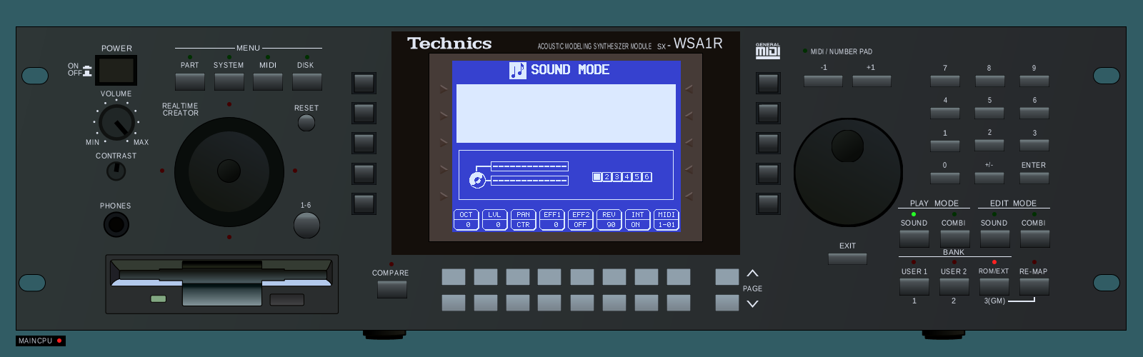
SOUND MODE with its parameter row (OCT / LVL / PAN / EFF1 / EFF2 / REV / INT / MIDI), reached without any input.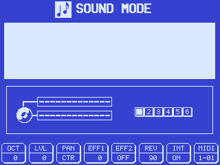
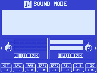
The keyboard variant draws two parameter panes where the rack draws one. That is the first screen-level confirmation that the two systems really are different machines and not a cosmetic split — the strap is doing visible work.
⚠ The colours are a driver choice, not a measurement (see palette_init()).
Only the glyphs are evidence.
The boot, in order
Every step below is read by a named probe in kn7000_mame/notes/wsa1-probes/,
and each probe states the question it answers; wsa1_boot_milestones.lua walks
the sequence.
| step | what happens |
|---|---|
RESET at 0xF826A9 |
watchdog off, ports, timers, chip selects, RAM cleared, then into prom_b through the thunk table |
| the 488 Hz tick starts | the 8-bit timer that every firmware delay is written against, counting at RAM 0x0080 |
the battery-RAM checksum pair at 0xF82C80 |
0x100 words summed from 0x007620 against (0x007FD2), then from 0x617800 against (0x007FD4) |
| the SC1 module opens the control-panel link | and the panel answers |
LCD_Init_SED1330 at 0xF8E822 |
the display controller is initialised — first write at t = 0.50 s |
| SWI7 text drawing begins | t = 19.62 s |
| CPU 2 reaches MAIN | its key scanner goes live |
the screen settles on SOUND MODE |
the panel carries drawn text and stops changing, while CPU 1 keeps running ordinary code across prom_a and prom_b — a live system sitting on a screen, not a hang |
(The two absolute times are from tlcs900_timer_control.sh on the current core.
They are meaningful only against a build whose timers are right — see below —
so re-measure rather than quoting them across a core change.)
Both checksums FAIL, and that is the right answer. The helper at 0xF82CD3
returns carry clear on a match and its callers only set a verdict bit on that
path, so in (0x007FD1) a set bit means PASS; the measured value is 0x00.
For a machine with no battery-backed contents, failing is correct.
★ A short run on this machine is not a null result, it is no result. The boot takes tens of seconds of emulated time before anything is drawn. Any probe that reports “the firmware never reaches X” from a run shorter than the boot is measuring its own timeout. Use
-str 120or more.
What this machine requires from MAME’s TLCS-900 core
Four behaviours in src/devices/cpu/tlcs900/ are load-bearing for this firmware,
and each is stated here with the evidence that fixes its value:
- The 8-bit prescaler taps are φT1 = fc/8, φT4 = fc/32, φT16 = fc/128,
φT256 = fc/2048 (Toshiba TLCS-900 Series CMOS 16-bit Microcontrollers
TMP95C061, Table 3.8 (1) p. 81), i.e. shifts of 3/5/7/11 on the prescaler.
They set the rate of the RAM
0x0080tick, which comes out at 488.3 Hz against the 488.28 the firmware computes for. - The 16-bit timers 4–7 must actually count, and must set
INTET54.INTTR4— vector0x50→0xF82EA2— is this machine’s musical clock, and it runs at 192.0 Hz. - Control register
0x3C, INTNEST, must exist and must be incremented on interrupt acceptance and decremented onRETI. Without it the UI never appears; see below. - P6 must be mapped to
PORT_6, notPORT_7.
The overlay’s tmp95c061 additionally carries a serial engine on channel 1
and INT6 / INT7 in execute_set_input(), neither of which exists upstream.
notes/wsa1-probes/tlcs900_timer_control.sh re-measures rates 1 and 2 against a
control build, which is how they are checked rather than assumed.
★ Control register 0x3C is what stands between two screens
IRQ_Epilogue (prom_a 0xF857B7) reads control register 0x3C and enters
the kernel only if it reads exactly 1; Kernel_Dispatch (0xF85715) reads it
again and refuses to reschedule unless it is 0. Both CPUs’ kernels use it — 10
accesses in prom_a, 9 in prom_c — so a core without the register never
reschedules and the draw task never dequeues.
It is implemented in the shared CPU core. The control that shows it is load-bearing is a build with no such register at all:
| control: no register | as implemented | |
|---|---|---|
pending-tick counter (0xBE) |
wraps at 253 Hz, never drained | 00 |
| semaphore 1 | count 02, wait queue empty |
count 00, queue occupied |
| task 2 | state 04, never runs |
state 03, blocked |
| callback ring | rd 0000, wr 0008 |
rd = wr = 0008 |
| LCD writes | 33,623, frozen from t = 20 | 80,460 ⚠ |
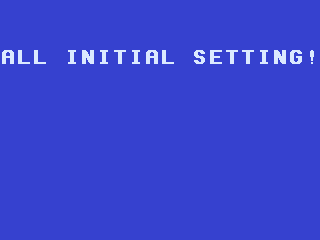
| screen | ALL INITIAL SETTING! |
SOUND MODE |
⚠ The LCD-writes row does not discriminate and is kept only for completeness. A control build with INTNEST implemented also ends at 33,623 LCD writes, so both explanations produce that number. The other five rows do discriminate.
⚠ The KN5000 is not affected, and that is a measurement rather than a symmetry
argument. tlcs900_intnest_evidence.py scans every ldc in all four SX-WSA1R
images and in the KN5000’s: the WSA1 uses cr 0x3C and never 0x7C, while the
KN5000 uses 0x7C and never reads it back — it keeps the nesting depth in a
RAM word at (1475) and only mirrors it into the register. So the same RTOS,
adapted to two family members. (The same scan shows the
SX-KN1500’s IC15 reading cr 0x3C with the same
4-read / 5-write shape — an observation, not yet a claim about its kernel.)
Why every core change here is gated on the KN5000
src/devices/cpu/tlcs900/ is shared by every tlcs900 driver in MAME, so a
change made for this machine can silently break a sibling. The standing gate is
therefore run on the built binary for every core change, and the row that
matters is not a pass count: it is the KN5000 demo-audio capture, which must
come back byte-identical to its pinned baseline. That capture is 90 emulated
seconds of the tone generator playing — tens of thousands of interrupts and
RETIs on the sibling TMP94C241 — so an identical WAV is a strong statement that
interrupt timing did not move.
What is modelled
| device | how |
|---|---|
| both TMP95C061s | MAME’s tmp95c061, at fc = 28 MHz |
| the 320 × 240 LCD | a real sed1330_device + screen. The geometry is the firmware’s own SYSTEM SET, written identically three times (30 07 00 27 35 EF 28 00), and two unrelated pieces of code agree with it — the coordinate clamps are 319/239 and the pixel plotter forms Y·AP + X/8 |
| the inter-processor link | byte port, strobe/busy handshake, micro-DMA channels 2 and 3 |
| the 61-key keybed scanner | 0x108000, with a touch-time adjuster |
| the panel microcontroller | HLE’d on serial channel 1, in wsa1_cpanel.cpp |
| the touch-calibration EEPROM | a 93C46-class serial part |
| the floppy controller | a real upd765a_device with a 3.5″ drive and PC formats |
the 0x7F0000 register file |
modelled as the 4 × 32 file its driver shape says it is, without a part name |
| the service CHECKING DEVICE | a switch plus a check_led output |
The control panel is wired, and it works in both directions. CPU 1 clocks out exactly the seven command frames the disassembly says the SC1 module sends first, in ROM order; the panel answers each; and pressing MENU DISK through the rack layout’s own binding opens the DISK menu and lights the DISK lamp. All 58 rack switches and 14 of its 18 lamps are bound. The full account — the schematic trace, the second witness in the ROM, and the receive-ring phase rule the HLE must obey — is on the Control Panel page.
The SED1330’s two runtime services differ in layer count, not geometry:
service 0x10 rebuilds the boot layout (three layers, OV = 1), service 0x0F
sets up two layers and clears exactly 0x6580 bytes = SAD2 + 240 × AP. The
overlay’s sed1330_device was changed to gate layer 3 on OV.
⚠ The SED1330’s clock is deliberately 0: its oscillator is a part this scan
does not resolve, and the device only uses clock() to re-derive the frame rate.
Leaving it at 0 keeps the screen’s nominal 60 Hz rather than deriving a refresh
rate from a crystal nobody has read.
The floppy controller is a upd765a_device, and here is why
Dev7A_StartDma (prom_a 0xFE596A) selects on ten command bytes, and every one
is a legal uPD765 command carrying exactly the MT/MFM flags that command may
carry: 0x4D FORMAT|MFM, 0xC5/0xC9 WRITE / WRITE-DELETED|MT|MFM,
0xC6/0xCC READ / READ-DELETED|MT|MFM, 0x42 READ TRACK|MFM, 0x4A READ
ID|MFM, 0xD1/0xD9/0xDD SCAN EQ/LE/HE|MT|MFM. Only 59 of the 256 byte
values are legal uPD765 commands, so ten arbitrary bytes all landing legal has
probability ≈ 4.2 × 10⁻⁷. The post-reset drain at 0xFE6891 is the textbook
SENSE INTERRUPT STATUS. The parts list has a uPD72070GF3BE, which has no MAME
device of its own; the family does.
⚠ 10/10 on the opcodes, but 7/10 on the direction: the three SCAN commands need a CPU→FDC data phase and sit in the device→RAM group. Recorded, not explained.
★ The fake that was deliberately not enabled
CPU 2’s uPD6383GF microcode upload polls the DSP’s READY line on P9 bit 3
(0xF9A19F: ld C,(0x19) / and C,0x08) at eighteen sites. MAME’s unbound
port read returns 0, so every byte of the upload burns the poll’s full 0x1F40
iteration bound and sets the firmware’s timeout flag. Measured: in a six-second
run, CPU 2’s program counter is concentrated in 0xF9A347-0xF9A399, inside
exactly that loop. That is where its boot time goes.
One line would make the handshake complete instantly:
m_cpu2->port9_read().set_constant(0x08);
It is not enabled, because it is a fake. No schematic net has been read for that pin, and the poll is bounded, so nothing hangs without it — it is only slow. Turning a measured stall into a fabricated ready signal would buy speed with a claim about the hardware that nobody has checked.
(P5 bit 4 is not a candidate for the same treatment: it is the service CHECKING DEVICE’s switch, and the manual says so in as many words.)
The keybed scanner works, and the link now carries the note
- The scanner works. Press C4 after t = 71 s and prom_c reads
0x5C98off0x108000, and0x5C18on release — touch0x5C, key 24, bit 7 for down — which is byte for byte what the driver queued. - The link carries it now. The CPU 2 → CPU 1 wedge — one packet, then stuck
on a handshake CPU 1 never released — was a CPU-core bug: a micro-DMA
channel’s
INT0was dispatched to the CPU instead of the channel it belonged to. It is fixed in the overlaytmp95c061(tlcs900_check_irqsnow skips an interrupt an armed micro-DMA channel owns — as thetmp94c241already did), plus a per-burst scheduling quantum so CPU 1 keeps up with the burst.
So a note now travels CPU 2 → CPU 1 → the link → CPU 2’s note engine → the tone
generator. MIDI IN is wired the same way (host MIDI → CPU 1’s serial channel
0 → the link → the note engine), and the tone generator turns the note into a
placeholder sine — verified end to end by feeding a .mid file to
-midiin and hearing it sound from ~t = 25 s. Real synthesis still waits on the
undumped wave ROMs.
The MIDI bridge is now validated in both directions, by a program outside the emulator
A .mid file on -midiin, an ALSA port on -midiout, and aseqdump — which knows nothing
about MAME — listening on the other end. Request in, reply out, no Lua and no memory taps:
the whole chain is midiin → the bit-serial bridge → CPU 1’s SC0 → the firmware’s
INTRX0 handler → its SysEx parser → the reply into ring 0x601432 → INTTX0 → SC0BUF
→ midiout. At the UART the five request bytes and the seven reply bytes are 320 µs apart
in each direction, which is 31250 baud, as it should be. (The responder is a
research patch rather than stock firmware — a stock
machine has nothing to answer with — but every emulated component in that chain is the
shipping one.)
⚠ midiin’s ten-second delay is an offset, not a deadline. MAME sets
m_sequence_start = std::max(machine().time(), attotime(10,0)) — “to allow the keyboards
to initialize” — and then plays the file from there, so an event stamped at T seconds
arrives at 10 + T. A run that is too short and a timestamp that is too late both look
identical from outside: an empty capture. This is emulator behaviour, not a driver bug; an
earlier reading of it as “the MIDI receive path is broken” was wrong.
Note-off makes a voice retire, through the firmware’s own path
A released note used to sound forever. The firmware frees a voice only after
the chip’s amplitude has decayed to silence — it learns that by polling the
tone generator’s busy bitmap (tg_status_r, select 0–3) and, for every channel
whose bit has fallen, writing 0x7E00 (FREE) — but nothing in the placeholder
made that bit fall, so note_long.mid piled voices into a rising drone (the left
channel’s RMS climbed monotonically to full-scale clipping).
There is no note-off gate bit at this interface: on note-off the firmware
leaves block 0 at its gate value and instead re-stages the amplitude envelope
with a release profile, from the retire walk (Voice_Retire_Mode20 →
Dev10C_WriteSixChanRegs_FromD78A, prom_c 0xFB7345). That burst writes
registers chan+{0x0800, 0x0840, 0x0900, 0x0940, 0x09C0, 0x0A00} — but not
chan+0x0A40, whose only writer is the note-on burst
(Dev10C_WriteAllChanRegs, its last register). The driver uses exactly that one
asymmetry: 0x0A40 marks the end of a note-on burst, so a later write to
0x0A00 on a still-gated channel is the note-off. The placeholder voice then
decays; when it reaches silence the driver drops the busy bit, and the
firmware’s own retire path writes 0x7E00 — the same sequence as on hardware.
No 0x7E00 and no envelope shape are fabricated. Verified with
tools/rigs/wsa1_wav_rms.py: before, a monotonic drone to clipping; after, each
note sounds and retires and the passage ends in silence.
A debug port into the machine
⚠ This is a research instrument, not emulation. It is a modified program ROM. No real SX-WSA1R has it, it must never reach a MAME pull request, and nothing on this page above this line depends on it. It is documented because the technique is reusable and because one of its findings — how a byte leaves on MIDI OUT — is ordinary firmware documentation that outlives it.
The µPD6383GF decode has a measurement problem: the interesting questions are about what individual microcode words do, and the only readout on a real WSA1R is analogue audio out of a machine whose wave ROMs are undumped. The instrument that would fix this is a bidirectional debug channel over MIDI — load a probe, read exact integers back — and the program ROMs are socketed, so a modified EPROM is physically possible.
What exists today, in the emulator, on a patched prom_a:
| size | 397 bytes, in 0xFBA236–0xFBA3C2 — a run of 2506 0x0E (RET) padding bytes that nothing in the ROM references |
| hook | one four-byte instruction. MIDI_RX_SysExData (0xFA586E) is called for every data byte of an accepted SysEx; its first four bytes f0 a9 c9 66 become jp 0xFBA246, and jp abs24 is exactly four bytes. The routine has one caller and is only ever entered at its first byte, so nothing after the patch is reachable. Restoring the ROM is a four-byte write — or putting the original chip back in its socket |
| state | one borrowed bit. (0xA9) is the firmware’s own SysEx state byte, and bit 5 is tested by MIDI_RX_SysExData and set nowhere in the firmware. Its lifecycle is exactly right: MIDI_RX_SysExStart does ld (0xa9),0x01, clearing it at every F0. It means “this message is mine”, which also makes the stock parser skip our bytes |
| commands | IDENT — F0 7E 7D 01 F7 → F0 7E 7D 7F 01 00 F7; PEEK — F0 7E 7D 02 <6 address nibbles> F7 → F0 7E 7D 7E <8 bytes as 16 nibbles> F7. MIDI data bytes carry seven bits, so each payload byte travels as two nibbles: wasteful and completely unambiguous, the right trade for a debug channel |
The patcher refuses to run unless four gates pass: the input hashes as the known prom_a
dump, the destination is all 0x0E for the payload’s length, the hook site still holds
f0 a9 c9 66, and the output differs in exactly the payload plus those four bytes. Two
independent toolchains agree on the result — llvm-mc assembles it and MAME’s own
unidasm reads the patched image back as the intended instructions.
The PEEK test is self-verifying. It is asked to read the eight bytes at 0xFBA236,
which is the monitor’s own reply table, so the right answer is known before the machine
starts. The reply nibble-decodes to F0 7E 7D 7F 01 00 F7 00. Byte for byte.
Three things make that a result rather than an anecdote, and the first version of the test had none of them:
- A negative control. The same stimulus against the unpatched ROM must produce no
reply — and
0x7Eis an identifier the stock parser accepts, so “the firmware answered by itself” was a live alternative, not a straw man. - The instrument is checked before it is read. An empty capture is not a result. The machine emits Active Sensing continuously, so the harness fails the run outright if the capture contains none; otherwise a disconnected listener would make the negative control pass for the wrong reason.
- It has been seen to fail — on the
midiintimestamp trap described above.
⛔ What it cannot do yet, and the reason is architectural
The next commands wanted are LOAD, POKE, RUN and DUMP — put probe microcode into a
µPD6383 and read the result. They are not extensions of PEEK. The monitor is patched
into prom_a, which is CPU 1; the three DSPs hang off CPU 2’s ports (P7 =
DSPD0-7, P5.3 = C/D, chip selects on P5.4/P5.5/P2.7). Between the processors is
only the octal-latch mailbox — the same link 0xF40ED4 writes to. So every DSP command is a
second agent on the other processor, speaking a protocol we would have to join. PEEK
is CPU-1-only, which is why PEEK came first.
Seven probe experiments, one per open axis of the instruction set, were designed and then put through a pass whose only instruction was to refute them. All seven were refuted, and the objections were not seven different objections — the wrong-CPU problem above is one of three that recur in every single design. The other two: there is no audio readback (the wave ROMs are undumped, so this machine makes no sound in MAME, and using the emulator’s model of the DSP to decide what the real chip’s instructions mean is circular); and several designs read their positive control through the very idiom under test, so “the poke never arrived”, “the instruction does not read the table” and “the instruction does nothing” collapse into one observation.
What survives is the cheapest item on the list: render the service manual’s effects-board
pages at ≥300 dpi and read IC30 pins 83–88 (RQ1-3/GF1-3 in the CDJ-500 pin table).
They may reach a latch the host can read, which arms two searches at once; they may be
strapped; they may be unconnected — in which case the honest report is “not available on
this board”, never “the chip has no such feature”. These are image-only scans: pdftotext
returns nothing on them and has already produced two false negatives on this project.
Findings flow in both directions
This machine is the clearest case on the site of a disassembly and an emulator feeding each other:
- the disassembly predicted
cr 0x3C, and the emulator confirmed it was what blocked the UI; - the emulator found the consumer of prom_c’s key-state bitmap at
0x0000FFF0— which the disassembly tree had looked for in prom_c and not found, because it is on the other processor.
kn7000_mame/notes/WSA1-EMULATION-DISASM-GAPS.md is the formal version of that
traffic: a ranked request list from the emulator to the disassembly, lettered
A–Y plus MAME-side items, each naming a question, what the driver does instead
today, and where to start looking. Roughly a third of the lettered gaps are
closed and several are closed on one side only, so read the note for the live
status rather than a list repeated here — it marks each entry closed, half
closed, or closed for one variant.
One result from that traffic is worth carrying: the CPU 2 → CPU 1 link wedge
was a CPU-core bug, and is now fixed (a micro-DMA channel’s INT0 was
dispatched to the CPU instead of the channel; see the keybed/link section above).
A separate CPU 2 stall — its uPD6383 READY poll (below) — is a different problem
and is not the inter-processor link.
What is still missing
| gap | state |
|---|---|
| Real synthesis | the tone generator plays a placeholder sine (wsa1_tonegen_device), scaled by the OUTPUT LEVEL register and silenced by the idle marker; the three DSPs, the modelling LSI’s internal signal path and the six wave mask ROMs are all absent or undumped, so the instrument’s real voice is not produced |
| Faithful release envelope shape | voice retirement now works (see below) — a released note decays and the firmware frees it — but the decay is a fixed placeholder ramp, not the real time-varying segment envelope, whose rate/level semantics are not yet established |
| The six wave mask ROMs | NO_DUMP. The manual gives their capacity (16 Mbit each) but not their organisation, and the scan does not resolve which sits on which of the tone generator’s address buses — so each gets its own region rather than being concatenated |
| The AM29F400T flash | not modelled; its data-poll and erase-verify loops are unbounded and will spin if reached |
| MIDI (in and out) | both directions now wired. tmp95c061 has a serial-channel-0 receive engine (sc0_rxd raises INTRX0) and, new, a transmit callback (sc0_txd, from sc0buf_w); a wsa1_midi_uart bridges MAME’s bit-serial midiin/midiout to CPU 1’s SC0 (the rear MIDI1 jack) in both directions. An external note reaches the tone generator, and the machine now transmits what the firmware sends — performance parameters as CC/aftertouch/pitch-bend as you play, plus bulk/group SysEx dumps and GM (-mdin/-mdout). A default-off “Live parameter mirror” option adds the one config value the firmware never emits on edit, tempo, as F0 50 25 <lo> <hi> F7 — see the live-sync analysis. ★ The bridge is now validated in both directions against an external program (above), so a MIDI-touching pull request can cite a round trip rather than an inspection |
| The panel MCU’s mask ROM | not dumped, and no ROM region is declared for it — the manual does not give its capacity, and guessing one would be worse than leaving it out |
0x104000 and 0x10C000 |
shapes established; the labels deliberately read Dev104_ and Dev10C_ rather than anything that would imply a function. For 0x104000 most of the register meanings are recovered — twelve names, six exact units, the whole map — but nothing in the driver acts on them, and the internal signal path is unknown. A behavioural HLE reference of the documented resonator model now runs outside the driver (wsa1/hle/, see the LSI page) — a realization of the model, not the chip’s audio, which still needs the wave ROMs and an internal-path trace |
| The drive motor line | the firmware does drive CPU 1’s PA bit 3 — four writes, the only bit of PA it changes after RESET, and it clears the bit (res 3,(0x1E) at 0xFE18EF) before a 307 ms spin-up delay. The driver still declines to wire it to the drive’s motor, because what the pin does is not claimed — a drive-motor or drive-select line is only the obvious reading. The consequence is stated rather than papered over: with no motor modelled, an attached image never becomes READY, and a read reports the firmware’s own error 0x31, drive not ready |
Reproducing any of this
Every measurement on this page comes from a committed probe in
kn7000_mame/notes/wsa1-probes/, and the directory’s README carries the run
recipe and two traps worth repeating:
- MAME’s Lua GC silently collects a tap or notifier not held in a global.
Every script there keeps its handles in
_G. - Taps on these 16-bit spaces must start on a word boundary. A tap on an odd single byte throws; cover the containing word and select the half with a mask.
- TLCS-900 registers are exposed bank-qualified —
XDE0…XDE3, never plainDE, socpu.state["DE"]is a nil index. Which bank is live depends onRFP.
The MIDI round trip uses no Lua at all, deliberately, because a real machine offers none:
kn7000_mame/tools/wsa1r-sysex-monitor/midi_roundtrip.sh builds the patched ROM, drives
IDENT and PEEK from generated .mid files, captures the replies with aseqdump, and
runs the stock-ROM negative control. WSA1R_MIDI_LOG=1 with -log adds a UART-level view
of every byte in and out.